In terms of CNC programming, feeds, tool management, and spindle management are essential. The three fundamental aspects that are contained in the CNC G-Code for feeds (feedrate modes, G94/G95), controlling the spindle (spindle command, (S, M03/M04/M05) (G96/G97), and tool-change and offset routines, (but not limited to) (T, M06, and G43) also control chipload, cutting temperature, and tool spatial orientation. Using the correct G-Code application lessens the chance of collision, optimizes surface finish and tool life, and optimizes machining cycle time to ensure predictable success and economic production.
Spindle Control (Speed & direction)
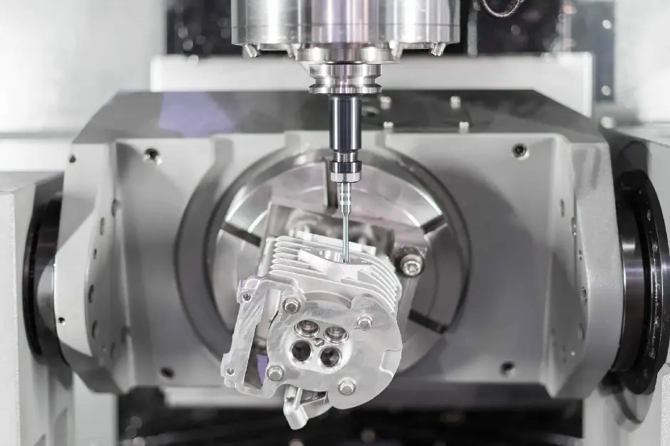
The aspect of CNC machining using precise spindle control is the key. When you are using a cutting tool (milling) or when you are spinning the workpiece (turning), your program (CNC/NC Toolkit) must provide you with the exact rotational speed and direction so that you can maximize efficiency, the life of the tool, and ultimately the quality of the part. Let's take a moment to review the G-code cylinders and some CNC recreation tools.
Basic Spindle Controls: S, M03, M04, M05
S - Spindle Speed:
This address provides the rotation value. It is important to note that once S is entered, the program will not activate the spindle without an initial direction command (M03/M04). The value entered inside the command relates to either:
- Direct RPM (Revolutions Per Minute): this is the default operating mode for milling machines (ex, S1200 = 1200 RPM). The range is usually from 1 to 9999 or 1 to 99999, depending on the machine. There is no decimal point.
- Cutting Speed (CSS): This setting is primarily utilized on lathes (activated through G96). The value represents surface speed (ex, S300 = 300 meters/min or feet/min). The control calculates the RPM based on the current diameter of the workpiece.
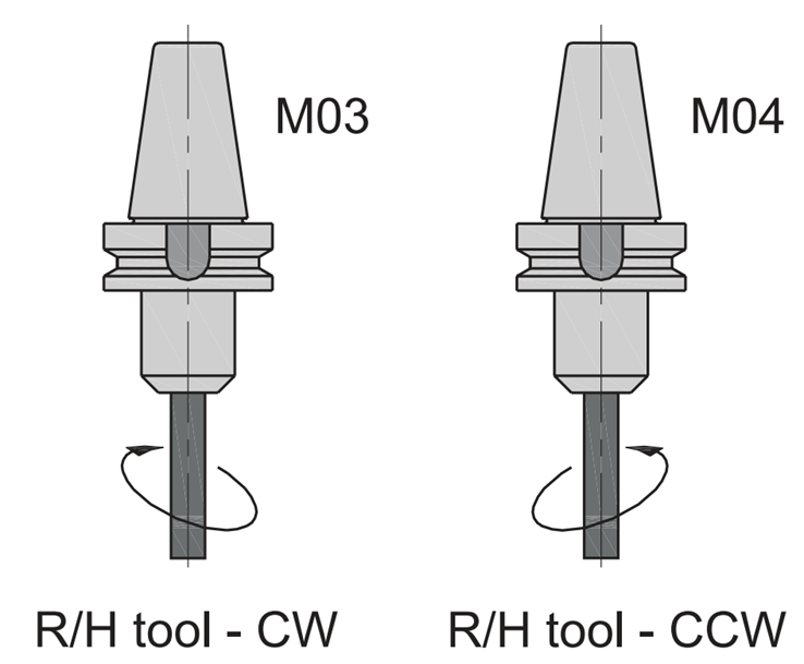
M03 - Spindle Start Clockwise (CW):
This setting is the default rotational direction for most cutting operations when the tool is right-handed.
M04 - Spindle Start Counterclockwise (CCW):
This setting is utilized for special operating situations (i.e., left-hand threading {always send machine CCW}, back boring, left-hand tool, etc.).
M05 - Spindle Stop:
This command stops the rotation. You should always program this command before you change tools, at the end of the programmed sequence (M30), or when you intend to change rotation direction. All CNC function controls contain a 'stop' sequence, like M00 (program stop). However, in order to clarify stop sequence commands, I would recommend you routine the M05 command for complete awareness of the spindle function command.
Defining Rotation Direction: It's All About Perspective
The terms Clockwise (CW) and Counterclockwise (CCW) are both perspective-driven. The standard reference point from which to determine CW or CCW is defined as looking from the machine stock (headstock) along the centerline of the spindle towards the spindle face (or chuck/workpiece). This perspective is maintained all the way from milling machines and machining centers to lathes.
Milling (Vertical Machining Center):
When looking "at the machine" (operator position) and looking towards the spindle head (the person has entered the machine through the front door), M03 (CW) appears as a clockwise rotation and M04 (CCW) appears as a counterclockwise rotation.
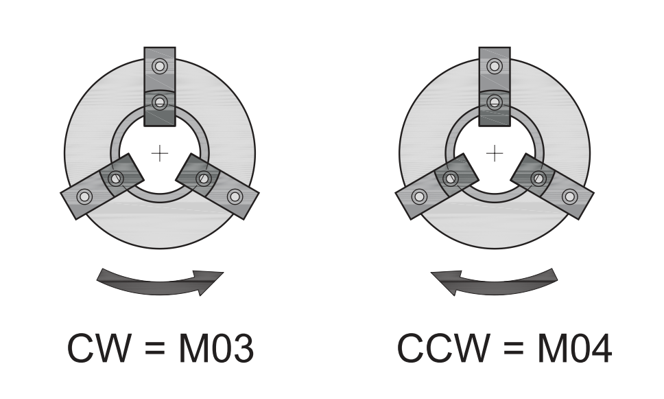
Turning (CNC Lathe):
The lathe exists in a rotation that may seem counterintuitive to a mill. But once you get used to the headstock viewing standard, it all makes sense:
- Correct View (Headstock -> Tailstock): When looking from the headstock to the chuck/tool, M03 (CW) rotates the chuck in the clockwise direction, and M04 (CCW) rotates the chuck in the counterclockwise direction. These definitions are the same as a mill.

- Incorrect View (Tailstock -> Chuck): Therefore, when looking from the tailstock to the chuck, it looks reversed (i.e., directions are transposed). This view should never be used for programming.
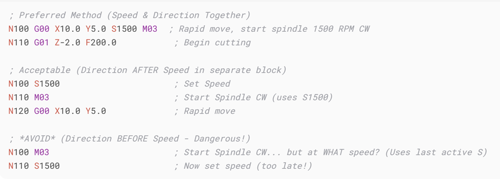
NB: Always program M03 or M04 with, or after, the S command in the same block (i.e. in G-code). Never program rotation direction before speed. If the previous speed is unwittingly used, it could also be dangerous.
Constant Surface Speed (G96) and RPM Mode (G97)
Lathes always deal with changing diameters, particularly with facing and turning. Thus, programming a lathe with a fixed RPM (S) to drive the rotations can be quite inefficient since the surface speed at the cutting tool could vary drastically depending on the diameter. G96 is the solution.
- G96 S - Constant Surface Speed (CSS):
Sets CSS mode. The S value is the desired surface speed (ex, meters/min or ft/min). The control computes and controls the spindle RPM automatically in real-time, throughout the cut, based on the current X-axis position ( ie, workpiece diameter). Therefore, this greatly improves the consistency of cutting conditions throughout the cut, improving tool life and surface finish.
- Example: G96 S300 M03 (set CSS to 300 m/min, start CW spindle).
- G97 S - Spindle Speed Mode (RPM):
Cancels G96, and the control will rely on RPM control instead of CSS. This is important for operations such as drilling, tapping, or reaming when the center line tool is at X0 (diameter=0), or when a fixed speed variable is critical. G97 is also used before G96 on some machines to produce a rapid acceleration to cut speed when the diameter is small.
- Example: G97 S1000 M03 (set spindle to 1000 RPM, start CW spindle).
Waiting for Spindle at Speed
Modern CNC controls will typically load the motion of the machine with the state command for readiness when the spindle reaches the commanded speed. With older machines or when the speed is critical and/or high, you may want to include a short dwell (G04 P) after the S M03/M04 block. This will ensure that the spindle has met its rated speed before cutting begins, so that damage to the tool and unacceptable surface conditions may be prevented at the initial engagement.
Feeds — Key Commands & Behavior
The commands that have the most association with feedrate are F, G94, G95, G93, G00, and G01.
The F Command -- Establishing the Feedrate
The F word specifies the cutting feed rate. The value of F is based on the current feed mode (per minute, per revolution, or inverse time). An important part of CNC programming is that F is modal; once the feed rate is set by an F command, it remains in effect until replaced by another F command. For example, if F200 (mm/min) is given, that applies to all future linear or circular cutting moves until changed.
The F word refers to the cutting feed rate. Its specified value is determined by the current feed modes, which could be in units of per minute, per revolution, or inverse time. An important detail for CNC programmers is that F is modal. Once set, the feed rate remains active until another F command cancels it. For example, the command F200 (mm/min) will apply to all subsequent linear or circular cutting moves until it is changed.
G94 — Feed per Minute
G94 will cause the control to interpret the feed rate as units per minute (mm/min or in/min). This is the most common mode for milling machines, as the feed rate is independent of the spindle speed. For example, G94 F300 indicates the tool will move at a feed rate of 300 mm/min regardless of RPM. This is helpful for many machining applications, especially when using cutters of different diameters, and for the consistency of surface finishes.
G95 — Feed per Revolution
G95 tells the machine to interpret feed in units of per revolution (mm/rev or in/rev). This feedrate mode is standard on lathes since the tool engagement is directly related to the rotation of the spindle. Using the example above, G95 F0.25 (mm/rev) indicates the tool will advance 0.25 mm for each spindle revolution. This is needed to ensure a consistent thickness of the chip, which is an important consideration in turning and threading.
G93 — Inverse Time Feed
G93 is a less common and understood mode, but valuable in some applications, particularly multi-axis or rotary type machining. This feed-rate mode interprets the feed value as the inverse of time (1/min). Effectively, the feed rate indicates how long the move will take to perform. Using the previous examples, G93 F2.0 indicates the programmed move will be completed in 0.5 minutes. This is very important when synchronization is needed for toolpaths during high-speed and/or simultaneous axes operations.
G00 vs. G01 — Rapid & Controlled Motion
G00 (Rapid positioning): Moves the tool at maximum speed for the machine, though not a "feed rate" in a cutting sense. It is critical to differentiate G00 from programmed feeds, since programmed feeds consider the "F" command. G00 should only be used for non-cutting moves, such as moving the tool to the position.
G01 (Linear interpolation): Provides controlled feed motion at programmed feed rate (F). G01 is the essential command for most cutting operations when both precision and material removal are to be achieved.
G94 or G95
The choice to use feed per minute (G94) or feed per revolution (G95) is based on the machining process to be used:
Milling: G94 is used most often when in doubt, since feed per minute will accommodate different cutter diameters.
Tuning: G95 is preferred since it ensures that feed is proportional to spindle speed, which assists in controlling the cutting conditions and increases tool life.
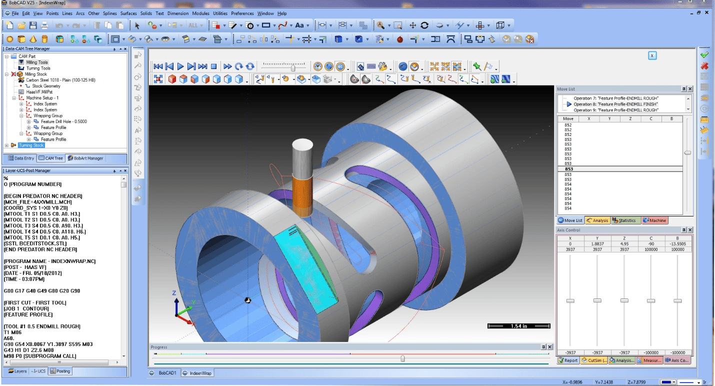
Tool changes & offsets
Tool retrieval and a safe tool change are essential components of dependable CNC programs. The T address is invoked to call a tool (on machining centers the T address is typically just made ready; the tool is actually exchanged with M06), and many modern automatic tool changers allow you to call the next tool (i.e., random-memory tool selection) so that the changer can preload the next tool while the current tool is cutting, and save chip-to-chip time.
The M06 function calls the automatic tool change routine; while many controls will stop the spindle during the M06 command, program an explicit spindle-stop (M05), and ensure that the machine axes are in safe positions before calling the M06 command, to prevent tool collisions, misses on clamps, and unexpected movements of the machine. At the same time, for multi-head tools (or long tools), be sure to elevate the Z with a machine move (G53 Z0 or G28 Z0) for clearance, just to be sure.
When the new tool is in the spindle, you have to apply tool length compensation so the controller knows where the cutting edge is positioned. Application is simple, it is just G43 Hn, which applies the tool length offset stored in register Hn (note that your H number must correspond to the tool offset index used). To cancel tool length compensation, use G49. After the tool change is made, ensure that the right H register is selected to avoid plunging into work offsets.
G28 and G53 are your safe-move friends. They can be used to move to machine coordinates (machine-zero) or a programmed parked position before changing tools – because they move in the machine reference, they will not be affected by active work offsets or modal tool compensation. This is how to ensure clearances to fixtures and the ATC when changing tools.
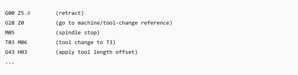
One-line best practice (mnemonic): retract → machine ref → tool change → apply offsets. Example pattern:
Machining Holes: Drilling, Pecking, Reaming, Tapping & Boring
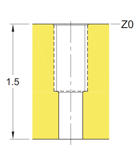
Hole-making is likely the most recurrent task in CNC machining, regardless of whether the intention is to mark bolt clearance, tap threads, or fit parts true to microns. Fixed cycles allow the operator to repeat a task simply through G81 (simple drilling), G82 (drilling with dwell), G83 (deep-hole peck drilling), G73 (high-speed peck), G84 (tapping), and G76 (precision boring).
- Drilling: A standard G81 cycle drops the drill directly down into the material. For deep or tough material, you want to remove chips and reduce the chance of breaking the tool by using other options of peck drilling (G83 or G73).
- Reaming: Start with a drilled hole that is slightly undersized, then accept the reamer to finish the size and polish the final surface finish. Coolant is important to keep the integrity of the surface.
- Tapping: When using G84, the feed must equal the thread pitch—this will synchronize the speed of spindle rotation and advance of the tool. Therefore, always calculate feed as spindle speed × pitch.
- Boring: Tighter tolerances or perfect concentricity are possible with boring—G76 will better suit where the tool will retract without confusing marks in the wall of the hole.
Patterns of Holes: Bolt Circles, Grids & Polar Layouts
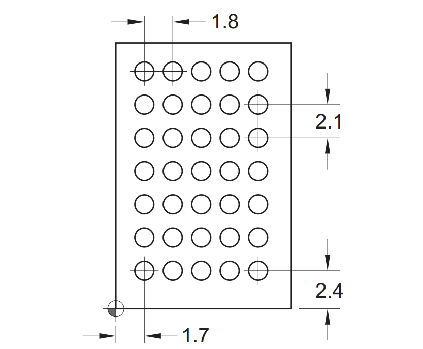
Rectangular pattern
Almost always, it is not just about one hole—bolt circles, grids, and polar layouts are prevalent in mechanical designing. Combine fixed cycles with some coordinate layout approaches to keep the programming to a minimum.
- Bolt circles: Bolt hole patterns may take advantage of built-in CNC macros or polar coordinates. Depending on the CNC control, you can set a radius from the centre, set the number of holes, and the starting angle, and the control will locate each hole.
- Grid: A rectangular array of holes can be programmed in conjunction with incremental moves (G91) or by looping a subroutine for normal situations.
- Polar coordinates: Some controls allow direct polar support, which makes programming of angular layouts easy.
For stability and overcoming chip control, use a logical sequence or pattern to surrogate additional holes—for example, machine every other hole, so chips can fall away, and reduce tool wear.
Face Milling: Tools and Strategy
Face milling allows for rapid machining of large, flat surfaces; a combination of the cutting speed and the quality of surface finish makes face milling the preferred process. The main factors to consider when face milling are the type of tool to use, the cutting direction, and how those two elements affect your strategy:
- Tool selection: In general, a face mill with multiple inserts will cover a large surface area quickly. If you have more restrictive work envelopes, you may find shell mills more applicable. For softer materials, like aluminum, you want to use sharp, polished inserts; for steels, inserts made from carbide (preferably coated inserts)—which are a little more expensive—have a longer life cycle than high-speed steels.
- Climb vs. conventional: Climb milling provides a better finish, fewer burrs, and better tool life as the cutter engages the material through the maximum chip thickness first. Conventional milling still has its purpose; if you are using an older machine that may have backlash, conventional milling is a safer means of investment.
- Step over strategy: The quickest way to machine a component is by overlapping "step-overs" (or work paths) at 60 to 70% of the tool diameter, which achieves productivity while maintaining a high surface quality.
- Single vs multi-pass: You can rough out most of the stock, removing considerable amounts of material in a single pass to achieve a rough surface finish. Then, in the finishing pass, make light passes to achieve accuracy, but also surface finish.
Contour Milling: End Mills & Cutter Compensation
Writing toolpaths for a part with contours, pockets, and profiles requires a degree of control over the tool's movement. Contour milling is primarily performed with end mills. When we talk about endmill tool selection, the shape/type of endmill is only part of the discussion; you also have to consider the material of the part, the desired wall finish, and the type of toolpath entry.
- Tool selection: Endmills with more flutes = stronger tools and better finish in harder material; endmills with fewer flutes = better chip clearance and lighter cuts used in aluminum. Consider using TiAlN-coated endmills if working in steel; they will double the life in steel.
- Entry methods: Create a ramp or helical cut into the material instead of plunging straight down. This reduces the stress and energy on the tool during entry and will help with chip evacuation.
- Cutter compensation (G41/G42): Cutter compensation allows the machine to offset the tool radius so the programmer can change the tool size without having to rewrite the code.
- Best practice: Leave stock when finishing on a contour cut path and after making a finished pass at full depth and light depth of cut, leave additional stock to reduce tolerances and establish a smoother finish.
Conclusion
Recognizing G-Code basics is essential for fast and safe CNC machining. All feed commands (F, G94, G95), spindle command (S, M3, M4, M5), and tool change commands (T, M6, G43) application is directly related to surface finish, tool-life, and safety in machining. If both feed modes (e.g. rapid and feed-rate), spindle speed and direction settings, and tool offset using (G43) are in alignment with the job being machined, there will be reduced errors and increased tool life and consistent part quality and consistency... which leads to productive and cost-effective CNC machine time.