

Quality control in CNC machining is not just an end-of-line task. If errors are only detected after production, the cost of scrap, rework, and lost machine time can be significant. For shops running high-volume or high-precision parts, waiting until final inspection is simply too late.
In-process checks provide a proactive layer of assurance. By verifying dimensions, monitoring tool wear, checking surface finish, and tracking spindle health during production, machinists can identify deviations early. This prevents minor issues from turning into full-scale defects and helps maintain consistency throughout the run.

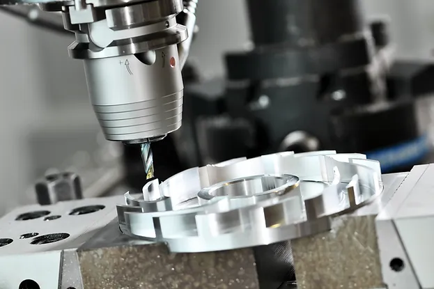
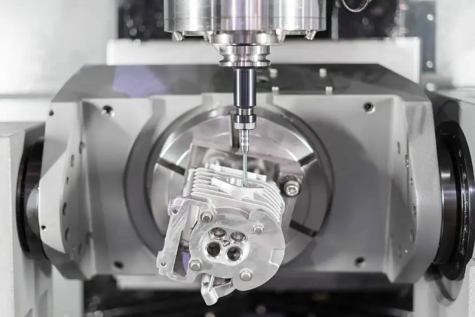
Quality Inspection of CNC Machining
This article explores the most essential in-process checks every shop should adopt. We will look at dimensional verification, tool wear monitoring, surface finish inspection, and real-time spindle and vibration tracking. Together, these checks create a systematic approach to quality that reduces waste, improves accuracy, and ensures every part meets its intended design.
Dimensional Checks During Machining
Maintaining dimensional accuracy during machining is at the heart of quality control. Even the most precise CNC program can only deliver good results if the process is constantly verified. In-process dimensional checks allow machinists to detect drift, adjust offsets, and confirm that every feature is within tolerance. Without these checks, the risk of cumulative errors increases, leading to assembly issues, wasted material, and missed delivery deadlines.

Importance of Dimensional Accuracy
Dimensional accuracy is the foundation of functional parts. When tolerances are ignored or poorly controlled, even small deviations can cause major problems downstream. For example, a hole drilled slightly undersized can prevent a bolt from seating, while a shaft cut oversized may seize in its housing. Such deviations are often not visible to the eye but become costly during assembly or field use.
Key reasons why dimensional accuracy matters:
- Ensures that parts meet design intent and function correctly in their application.
- Prevents mismatches that cause failures in assemblies, especially in aerospace, automotive, and medical industries.
- Minimizes the need for secondary operations, reducing cost and lead time.
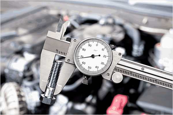
Tools for Dimensional Checks
After understanding why dimensions matter, the next step is selecting the right measuring tools. Each tool has its role depending on the feature, tolerance, and speed of verification required.
- Calipers: Suitable for quick checks of external, internal, and depth dimensions. They offer versatility but are best used for tolerances above ±0.02 mm.
- Micrometers: Provide higher precision than calipers and are preferred for critical features such as shaft diameters, thickness, and stepped features.
- Gauges: Go/no-go gauges are excellent for rapid inspection of high-volume parts where speed matters more than recorded measurement values.
- Height gauges and coordinate measuring machines (CMMs): Useful for setup verification and detailed checks of complex geometries when tolerances are extremely tight.
Timing and Frequency of Checks
The value of dimensional checks lies not only in the tools but also in when and how often they are applied. Checking too infrequently risks letting errors accumulate, while over-inspection wastes valuable cycle time.
Best practices include:
- Initial verification after setup: Always measure the first part after setup to confirm tool offsets, fixture alignment, and machine calibration.
- Periodic checks during production: Inspect parts at fixed intervals to monitor tool wear, thermal growth, and machine stability. The interval depends on tolerance requirements and batch size.
- Sampling versus full inspection: For tight tolerances or safety-critical parts, 100 percent inspection may be required. For general production, statistical sampling is often sufficient.
Best Practices for Accurate Measurement
Accurate measurement is not guaranteed by tools alone. The environment, technique, and consistency of operators influence results. Shops that ignore these factors risk unreliable data and inconsistent quality.
Practical guidelines for reliable measurement include:
- Calibration: Keep all instruments calibrated on a schedule to avoid gradual drift in accuracy.
- Controlled environment: Perform measurements under stable temperature and humidity to minimize thermal expansion of both parts and instruments.
- Proper technique: Train machinists to apply consistent measuring pressure and avoid parallax errors.
- Data recording: Log measurements to track variation trends. This data can highlight patterns, such as tool wear or spindle drift, before they cause failures.
Tool Wear Monitoring During Machining Cycles
Even the best cutting tools degrade over time. Wear is unavoidable, but uncontrolled wear compromises dimensional accuracy, surface finish, and machine health. By monitoring tool condition during machining, operators can intervene before defects occur. This proactive approach reduces downtime, protects expensive tooling, and ensures consistent part quality.
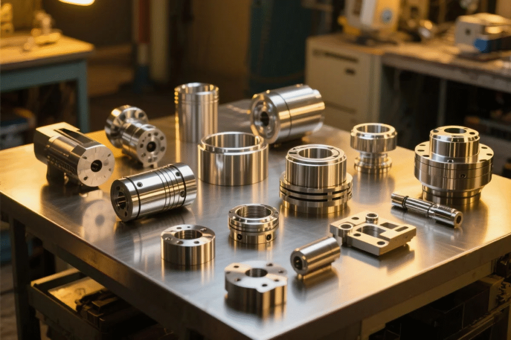
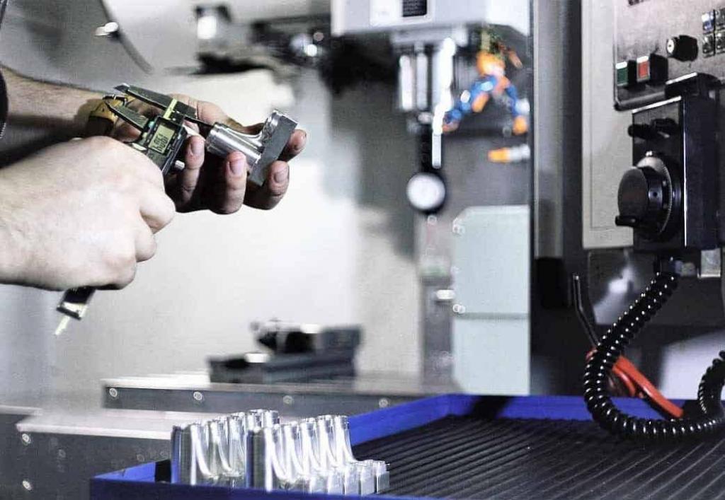
Quality Control Options for CNC-Machined Parts
Why Tool Wear Matters
Tool wear directly influences the outcome of machining operations. As cutting edges dull, they require more force to cut material, which in turn generates heat, vibration, and stress on both the tool and the workpiece. This gradual degradation is often subtle, but its impact accumulates quickly.
Key consequences of neglecting tool wear:
- Loss of dimensional control: Dull tools create oversize bores, undersize slots, and tapered edges.
- Poor surface quality: Worn edges, tear material instead of cutting cleanly, leaving scratches or chatter marks.
- Reduced tool life: Running tools until failure risks catastrophic breakage, which may damage the part, the fixture, or even the spindle.
- Increased operating costs: Extra rework, higher scrap rates, and premature tool replacement all raise production expenses.
Methods of Tool Wear Monitoring
Once the importance of wear is recognized, the next step is to choose reliable monitoring methods. Shops often combine simple manual checks with advanced systems to balance cost and efficiency.
- Visual inspection: A quick method suitable for smaller shops. Operators check edges for rounding, chipping, or discoloration. While inexpensive, results depend heavily on operator experience.
- Process parameter monitoring: Many CNC machines display spindle load, feed rate, or torque. A rising spindle load or sudden fluctuation often indicates wear or impending failure.
- Automated monitoring systems: Advanced systems use sensors to track cutting forces, vibrations, or acoustic signals. These provide real-time alerts, allowing operators to pause machining and replace tools before failure.
- Tool life counters: Software-based counters track cutting time per tool and flag replacements based on predefined thresholds. This method works well for predictable operations with consistent materials.
Integrating Tool Wear Data into Production
Monitoring data is only valuable if it is integrated into the workflow. Collecting numbers without acting on them leads to the same problems as ignoring wear entirely. Shops that formalize tool wear management can achieve significant gains in uptime and reliability.
Effective integration strategies include:
- Scheduled tool changes: Replace tools at defined intervals, before reaching critical wear levels. This prevents sudden breakage and unplanned stoppages.
- Predictive maintenance: Use sensor data and historical wear trends to anticipate tool replacement. Predictive systems reduce downtime compared to rigid schedules.
- Material-specific tracking: Record tool wear patterns for each material type and cutting condition. For example, cutting stainless steel often dulls tools faster than aluminum. Such insights help optimize feeds, speeds, and tool selection.
- Centralized data collection: Logging wear data across multiple machines allows supervisors to identify patterns, standardize tool change intervals, and negotiate better tool supply strategies.
Surface Finish Verification Mid-Production
Surface finish is more than appearance. It directly affects how a part performs in service, how it interacts with mating components, and how long it lasts. A part that meets dimensional tolerances but has poor surface quality may still fail in assembly, wear out quickly, or cause customer dissatisfaction. Mid-production surface checks allow shops to maintain process control, spot issues from tool wear or incorrect feeds, and make timely adjustments before an entire batch is compromised.

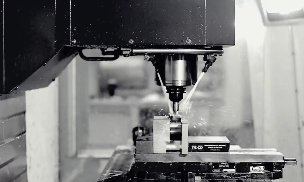
Surface Finish in CNC Machining
Role of Surface Finish in Part Quality
Surface finish defines the texture of a machined part at the microscopic level. While the eye may only detect scratches or chatter, precision applications demand a controlled level of smoothness or roughness. A properly finished part reduces friction, ensures tight fits, and supports long-term performance.
Functional reasons why surface finish matters:
- Aesthetics: For visible parts, a poor finish creates the impression of low quality.
- Assembly: Tight-tolerance fits, such as press-fitted shafts, rely on consistent finishes.
- Friction and wear: Bearings, gears, and sliding surfaces need smooth contact to reduce heat and extend service life.
- Sealing capability: Rough or uneven finishes on flanges or sealing faces can lead to leaks under pressure.
Measurement Techniques
Once the importance of finish is established, measuring it accurately becomes critical. Relying on eyesight alone is insufficient for most production standards. Different methods offer different levels of accuracy, speed, and cost.
- Visual inspection: The most basic approach. Operators look for scratches, burrs, or chatter marks during setup and first-off checks. While not quantitative, it is useful for catching obvious defects.
- Contact profilometers: Widely used in manufacturing, these devices use a stylus that moves across the surface to measure average roughness (Ra) or other parameters. They provide precise readings but require handling time.
- Non-contact methods: Optical or laser-based sensors scan surfaces without touching them. These systems are faster, reduce the risk of damaging delicate parts, and can be integrated into CNC machines for real-time monitoring.
- Comparator plates: For quick shop checks, machinists may compare a part’s finish against standardized reference plates. While less precise, it gives an immediate sense of whether a finish is within acceptable limits.
Frequency and Sampling
Knowing how often to check the finish is just as important as knowing how to measure it. Too many checks slow production, while too few risk passing bad parts. The balance depends on the application and tolerance.
Practical guidelines include:
- First-off verification: Always confirm surface finish during setup before committing to full production.
- Periodic checks: Inspect at regular intervals to detect tool wear, coolant issues, or vibration changes that affect finish.
- Critical features: Increase frequency of inspection on surfaces that affect functionality, such as sealing areas or bearing journals.
- Sampling strategy: For non-critical surfaces, inspect samples at defined ratios, for example, one in every 20 parts.
Corrective Actions
When surface finish drifts out of tolerance, immediate corrective action is necessary. Ignoring small deviations often results in entire batches needing rework.
Common actions to restore finish quality:
- Replace or re-sharpen cutting tools: Worn edges leave rough marks on the surface.
- Adjust machining parameters: A slower feed rate, optimized spindle speed, or increased coolant flow can restore finish quality.
- Check machine stability: Excess vibration or fixture looseness may create repeating marks on parts.
- Verify coolant condition: Old or contaminated coolant reduces lubricating ability, leading to rougher finishes.
Real-Time Spindle and Vibration Monitoring
The spindle is the heart of every CNC machine. Its performance directly determines accuracy, surface finish, and production efficiency. Even a small imbalance or misalignment in the spindle can create cascading effects, from chatter marks on parts to premature tool failure. Real-time monitoring of spindle behavior and vibration levels allows machinists to detect issues early, minimize downtime, and safeguard both the machine and the workpiece.
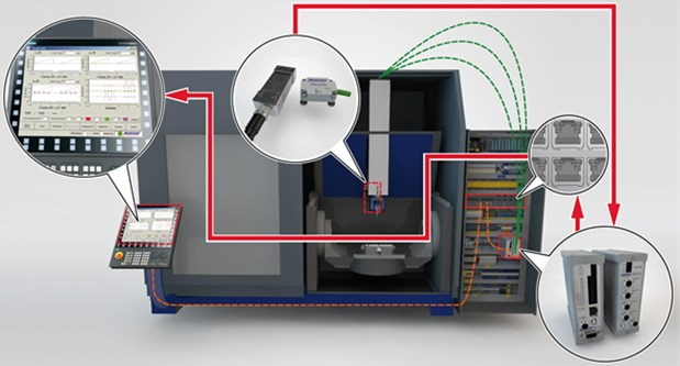
Vibration monitoring of CNC machinery using MEMS sensors
Importance of Spindle Health
A well-maintained spindle ensures stable cutting conditions. If the spindle begins to deteriorate, accuracy drops, and unexpected failures become more likely. Unlike tool wear, spindle issues can affect every part produced until the problem is addressed.
Reasons why spindle health must be monitored:
- Accuracy: Spindle runout or misalignment leads to dimensional errors.
- Surface finish: Unstable spindles leave chatter and waviness on surfaces.
- Cycle time: Machines may need to run slower to compensate for instability, reducing productivity.
- Cost of failure: Spindle repairs are expensive and often result in extended downtime.
Vibration as a Quality Indicator
Vibration is one of the most reliable indicators of spindle condition. Excessive vibration often signals imbalance, misalignment, or worn bearings. It also reflects problems with the cutting process itself, such as poor tool holding or unstable fixtures.
Consequences of ignoring vibration include:
- Reduced tool life due to uneven cutting forces.
- Loss of dimensional accuracy caused by oscillating tool paths.
- Poor surface finish from chatter or irregular marks.
- Potential long-term damage to the spindle assembly.
Monitoring Techniques
Monitoring spindle condition has advanced beyond manual checks. Today, a combination of sensors and software provides real-time insights into machine behavior.
- Accelerometers and vibration sensors: Installed on the spindle or toolholder, these sensors detect oscillations across different frequencies. Abnormal spikes point to imbalance, misalignment, or bearing wear.
- Spindle load and RPM tracking: CNC controls often display load and speed data. A gradual increase in spindle load can indicate tool wear, while sudden spikes may suggest instability.
- Acoustic sensors: By listening to the sound signature of cutting, these sensors detect chatter before it becomes visible on the part.
- Software dashboards: Modern systems analyze data from multiple sensors and display trends. Alerts can be set up to notify operators when vibration exceeds safe thresholds.
Actionable Insights from Data
Collecting vibration and spindle data is only valuable if it leads to action. A well-structured monitoring system not only alerts operators but also guides them toward the right response.
Examples of actionable uses:
- Stop or adjust machining: If vibration spikes, operators can pause the cycle, inspect the setup, and prevent defective parts.
- Optimize cutting parameters: Adjust spindle speed or feed rate to find a stable cutting zone with minimal chatter.
- Plan predictive maintenance: Schedule bearing replacement or spindle service based on real-time condition data rather than waiting for failure.
- Improve process knowledge: Analyzing trends across materials and operations helps fine-tune machining strategies for long-term consistency.
Integrating In-Process Checks into CNC Workflow
In-process checks provide the most value when they are built into the machining workflow, not treated as separate add-ons. A systematic approach ensures that every critical element, dimension, tool wear, surface finish, and spindle health is verified consistently without disrupting productivity. When checks are properly integrated, quality control becomes part of the machining rhythm, reducing errors while maintaining efficiency.
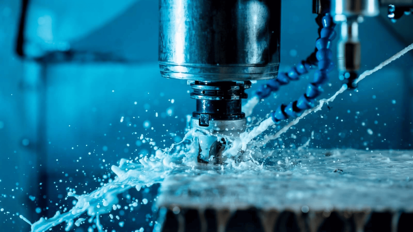
In-Process Inspection In Manufacturing
Building a Quality Checklist
The first step is to create a checklist tailored to each machining cycle. This should not be a generic form but a process-specific guide that identifies which features, tools, and parameters require monitoring.
A good checklist typically includes:
- Dimensional features to verify at setup and during production.
- Tools with high wear rates need closer monitoring.
- Surfaces that require finish inspection.
- Machine parameters such as spindle load, vibration levels, or coolant condition.
By embedding these checks into the operator’s routine, errors can be caught early without relying on memory or guesswork.
Combining Data Sources
Each type of in-process check provides valuable information, but the true strength comes from combining them. A dimensional shift may be explained by tool wear, while poor surface finish could be traced back to vibration. Connecting the dots allows for more accurate root cause analysis.
Benefits of integrating multiple data sources:
- Comprehensive insight: Data from measurements, sensors, and inspections creates a complete view of process health.
- Faster troubleshooting: Operators can identify whether issues stem from the tool, the machine, or the setup.
- Continuous learning: Storing results over time builds a database that supports process improvement.
Embedding into Daily Operations
Checks must be practical to be sustainable. If inspections are too time-consuming, operators may skip them under pressure. The goal is to integrate checks so naturally that they feel like part of the machining process.
Practical integration strategies:
- Setup stage: Verify first-off dimensions, tool offsets, and initial surface finish before approving production.
- In-cycle pauses: Program scheduled stops for sampling measurements without disrupting workflow.
- Operator responsibility: Train machinists to own the process by linking in-process checks directly to their production goals.
- Digital logging: Use shop-floor software to record results quickly, reducing paperwork while ensuring traceability.
Proactive Quality Control Outcomes
When in-process checks are fully integrated, quality control becomes predictive rather than reactive. Instead of waiting for defects to appear, operators can anticipate problems and adjust before they affect parts.
Key outcomes include:
- Lower scrap and rework rates.
- More consistent production runs.
- Increased trust between production teams and quality inspectors.
- Predictable lead times that improve customer confidence.
Benefits of Effective In-Process Checks
In-process checks are not just about preventing defects. They reshape the entire production environment by making quality control proactive instead of reactive. A shop that embraces these checks sees benefits that extend beyond the machining cycle. From reduced scrap to stronger customer relationships, the gains are both immediate and long-term.

CNC Machining Quality Inspection
Reduced Rework and Scrap
One of the most direct benefits is minimizing wasted time and material. When checks are performed mid-cycle, problems are caught before they multiply. Instead of discovering dozens of defective parts at final inspection, operators can stop after one or two.
Key advantages include:
- Material savings: Less scrap means more efficient use of expensive metals like titanium or stainless steel.
- Time efficiency: Detecting errors early reduces the hours spent re-machining or repairing faulty parts.
- Faster delivery: Avoiding last-minute rework ensures projects stay on schedule.
Increased Machine Uptime and Tool Life
Machines and tools last longer when monitored carefully. A worn tool that breaks unexpectedly can damage fixtures or the spindle, leading to extended downtime. In-process checks prevent such failures by encouraging timely interventions.
How uptime improves:
- Planned tool changes reduce unexpected stoppages.
- Healthier spindles and bearings extend the lifespan of the machine.
- Optimized cutting conditions based on real-time data minimize tool stress and prolong edge sharpness.
Consistent Part Quality and Customer Satisfaction
For customers, quality is not negotiable. Consistency builds trust and reduces costly disputes over defective shipments. By using in-process checks, shops ensure every part meets expectations, not just a random sample.
Customer-facing benefits:
- Reliable deliveries: Clients receive parts that pass inspection without exception.
- Brand reputation: Consistency strengthens the shop’s image as a dependable supplier.
- Reduced returns: Fewer defective parts mean fewer warranty claims and complaints.
Data-Driven Process Improvement
Another benefit often overlooked is the value of the data collected. Every recorded measurement, surface finish reading, or vibration trend contributes to a larger knowledge base. Over time, this data helps refine machining strategies and predict future challenges.
Practical uses of data:
- Trend analysis: Identifying which tools or materials cause recurring issues.
- Process optimization: Adjusting speeds, feeds, or coolant strategies based on recorded results.
- Predictive planning: Anticipating machine maintenance before problems occur.
- Training support: Using real data to train new operators on common pitfalls and solutions.
Financial and Strategic Advantages
The operational gains of in-process checks directly support financial performance. Shops that reduce scrap, extend tool life, and improve reliability position themselves better in competitive markets.
Business-level advantages include:
- Lower production costs: Efficiency gains reduce material and labor expenses.
- Improved profitability: Saving on rework and downtime increases margins.
- Competitive edge: Shops known for consistent quality win repeat contracts and attract high-value clients.
- Sustainability: Reduced scrap and energy use align with environmental goals, an increasing factor in supplier selection.
Conclusion
Quality in CNC machining is built on more than accurate programming and precise machines. It depends on what happens during production. In-process checks create the bridge between setup and final inspection, ensuring that every part produced remains within specification. By monitoring dimensions, tool wear, surface finish, and spindle behavior, machinists can respond to issues as they develop rather than after defects have accumulated.
The value of this proactive approach extends beyond preventing errors. It reduces scrap, increases machine uptime, extends tool life, and delivers consistent part quality. Just as important, it provides data that drives continuous improvement and strengthens customer trust. In competitive industries where deadlines and precision are equally critical, these benefits make a measurable difference.
Shops that integrate in-process checks into their daily workflow do more than protect against mistakes. They build a culture of reliability and accountability. Every operator becomes part of the quality process, and every cycle becomes an opportunity to verify, adjust, and improve. The result is not only fewer defects but also stronger performance and reputation in the long run.

