


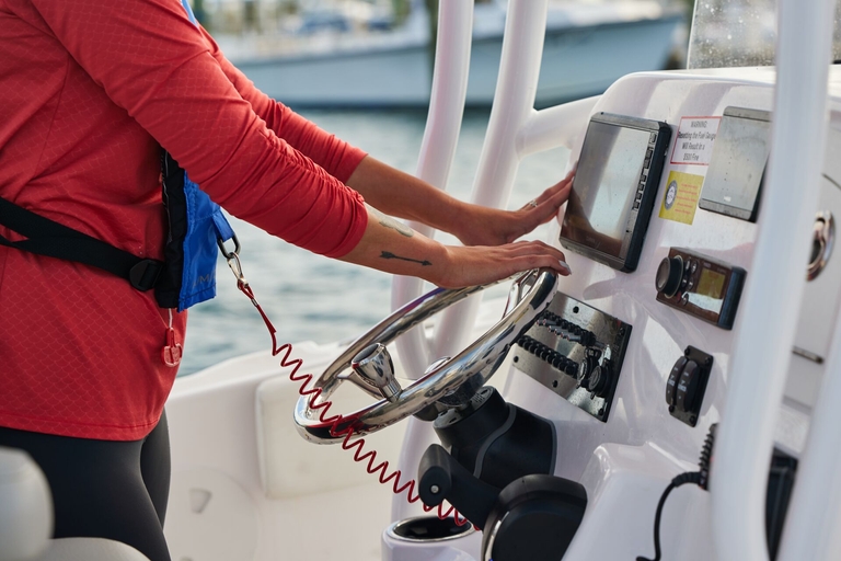
Steering is one of the most critical aspects of a vessel, yet most sailors rarely think about the hidden hardware that makes it possible. Behind the wheel or tiller lies a system of components working in unison, and at the very core of that system are the tiller head and the quadrant. These parts may seem like simple mechanical fittings, but they are the direct link between the sailor’s input and the rudder’s movement. A well-engineered tiller head or quadrant ensures that every adjustment at the helm is transferred with accuracy, giving the skipper full confidence that the boat will respond exactly as intended.
I’ve seen firsthand how even a small amount of play or misalignment in these parts can cause problems. A friend’s cruising yacht once developed a slight lag in steering after a quadrant worked loose on its shaft. At first, it was barely noticeable, but in rough seas, the delay became unnerving, steering corrections felt sluggish, and the boat wandered off course before responding. What seemed like a minor mechanical issue quickly revealed itself as a real safety risk. Precision in these components isn’t just a technical detail; it’s the difference between smooth, reliable handling and dangerous unpredictability on the water.
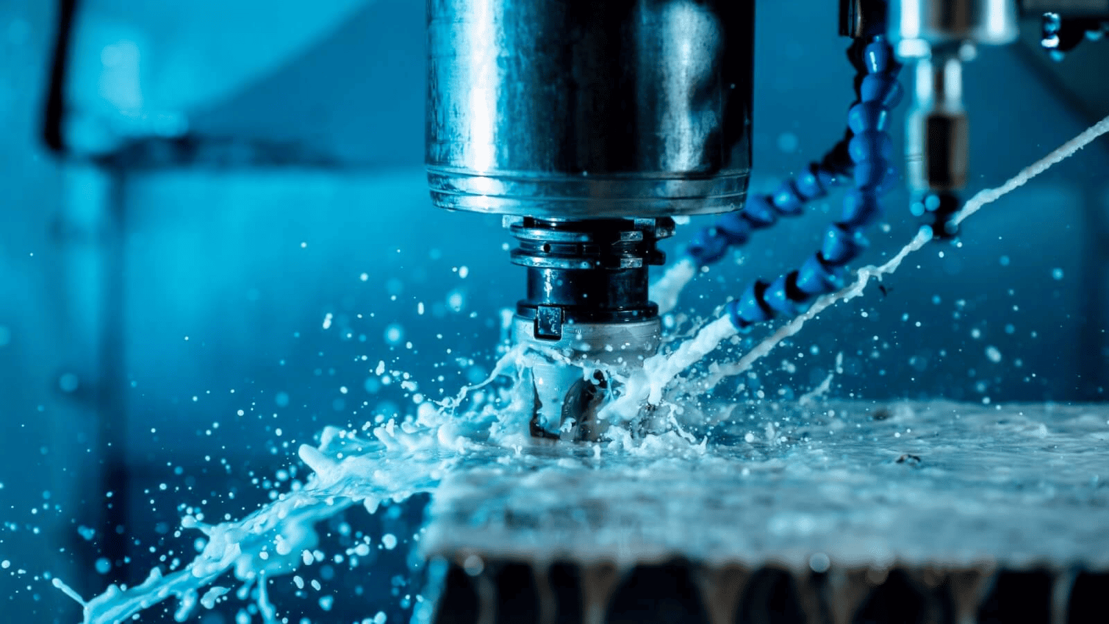
This is where CNC machining has redefined what’s possible in marine steering. Unlike traditional cast parts, which can suffer from imperfections and inconsistencies, CNC-crafted tiller heads and quadrants are built with uncompromising accuracy. Every bore, every pivot, every surface is machined to exact tolerances, ensuring long-term durability and flawless operation.
In the following sections, I’ll break down why this level of precision matters, how CNC processes improve steering gear performance, and what materials and design choices make the biggest difference for sailors who demand both reliability and peace of mind at sea.
The Role of Tiller Heads and Quadrants in Steering
In any marine vessel, steering is more than just turning a wheel or pushing a tiller; it’s a carefully engineered system designed to transmit input from the helm to the rudder with maximum efficiency and minimum loss of motion. At the center of this system are two critical components: the tiller head and the quadrant. Though compact in size compared to the entire steering assembly, these parts dictate how faithfully helm commands are translated into rudder action. Their role may seem straightforward, but their precision directly determines how the vessel feels under hand.
Function in Transmitting Helm Input to the Rudder
The tiller head connects directly to the rudder stock or shaft, serving as the clamping point where helm movement begins. In wheel-steered systems, the quadrant is attached to the rudder stock and links to the steering cables or chains that run back to the helm. Together, they form the mechanical bridge between human input and hydrodynamic response.
- A tiller head ensures a secure grip on the rudder shaft, maintaining alignment under high loads.
- A quadrant transfers rotational force from steering cables or hydraulic rams, converting helm torque into rudder motion.
When designed and fitted correctly, these components allow steering inputs to flow seamlessly, preserving both responsiveness and accuracy.

The Importance of Pivot Points and Shaft Interfaces
At the heart of steering mechanics lie the pivot points and shaft interfaces. These are the contact surfaces where movement occurs under continuous stress. If tolerances are tight and surfaces are correctly aligned, motion is smooth and predictable. However, even small deviations can introduce friction, play, or binding, each of which degrades steering quality.
- Tight pivots → smooth action, minimal wear.
- Loose fits → steering lag, clunking, and accelerated damage.
- Misalignment → uneven loading on bearings, reduced service life.
These fine details explain why high-precision machining is indispensable. A boat’s handling characteristics are only as good as the fit of its steering interfaces.
Consequences of Imprecise Components
When tiller heads and quadrants are produced with poor accuracy, the results are quickly felt at sea. Some common consequences include:
- Steering play: Extra movement at the helm before the rudder responds.
- Binding: Stiff or jerky steering action due to uneven bore alignment.
- Excessive wear: Loose fits that wear out shafts, cables, or bearings prematurely.
- Fatigue failures: Stress concentrations that lead to cracking in cast quadrants.
In critical situations, such as maneuvering in strong currents, docking in confined harbors, or steering in heavy weather, these shortcomings can compromise safety. For long-distance cruisers and racing sailors alike, precision is not a luxury but a necessity.
Why Precision Matters for Handling and Safety
A well-machined tiller head and quadrant give the helm an immediate, connected feel, almost as if the boat itself is alive in the sailor’s hands. Precision eliminates wasted motion, minimizes energy loss, and provides confidence that every helm input counts. Conversely, imprecise components force the sailor to overcorrect, create unpredictability in rough seas, and add stress to already demanding situations.
This is why boatbuilders and professional repair yards increasingly specify CNC-machined steering components. Unlike cast or roughly finished parts, CNC-crafted tiller heads and quadrants ensure every pivot, bore, and surface is held to tight tolerances. The result is a steering system that performs reliably not just during calm sailing but under the toughest sea conditions.
Tolerance Control in Steering Gear Pivot Points
The steering system of a vessel operates under continuous and variable loads, and the smallest deviations in geometry can compromise its reliability. Among the most critical aspects of this system are the pivot points, the joints, bores, and contact surfaces that allow controlled rotation of the rudder shaft and its connected components. Tolerance control in these areas is not just a matter of engineering discipline; it directly impacts steering precision, wear resistance, and ultimately, safety at sea.
Why Tight Tolerances Matter in Steering Systems
In engineering, tolerance refers to the permissible variation from a specified dimension. While in less demanding machinery, a few hundredths of a millimeter may not be significant, in marine steering systems, such deviations can lead to measurable inefficiencies. A quadrant bore oversized by even a fraction results in steering play; a pivot pin slightly misaligned introduces binding forces that multiply over time.
Tight tolerances ensure:
- Predictable movement: Smooth, uniform rotation without excess play.
- Load distribution: Forces are evenly spread across surfaces, preventing localized stress.
- Reduced wear: Accurate fits minimize frictional hotspots.
- Long-term reliability: Steering components last longer under cyclic loads.
Without strict tolerance control, every helm input risks being delayed, dampened, or distorted.
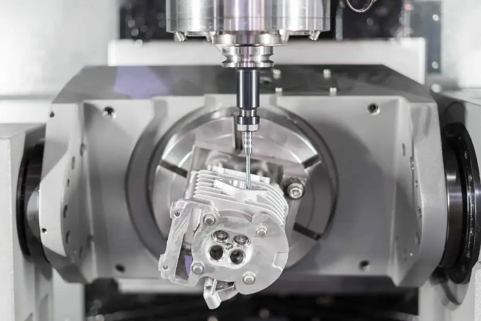
CNC Machining Advantages in Achieving Consistency
Traditional casting and manual machining methods often struggle to achieve consistent tolerances, especially across multiple production runs. CNC (Computer Numerical Control) machining eliminates much of this uncertainty by relying on programmed precision rather than operator judgment.
Key advantages include:
- Repeatability: Identical parts can be produced with minimal deviation, critical for fleets or standardized builds.
- Micron-level accuracy: CNC machines routinely achieve tolerances as fine as ±0.01 mm.
- Complex geometry control: Multi-axis CNC machining can handle compound curves and bore angles that manual methods cannot.
This consistency ensures that every tiller head or quadrant leaving the workshop performs to the same standard, without the variability that has long plagued cast components.
Measurement Methods and Quality Control
High-precision machining alone is not sufficient; it must be paired with rigorous inspection. Modern quality control techniques provide measurable assurance that components meet design intent.
Common methods include:
- Coordinate Measuring Machines (CMM): Capture exact 3D geometry and confirm dimensional accuracy.
- Dial bore gauges: Measure bore diameters to check shaft fits.
- Surface profilometry: Ensures pivot surfaces are smooth enough to reduce friction without removing critical material.
- Go/No-Go gauges: Quick checks for shaft insertion tolerances.
These inspection tools allow manufacturers to validate tolerances not just at the prototype stage but throughout batch production, ensuring that each component is seaworthy before installation.
Examples of Tolerance Specifications in Marine Steering Gear
While tolerance requirements vary depending on vessel size and steering design, typical benchmarks in marine applications include:
- Rudder shaft bores: ±0.02 mm on diameter to ensure interference-free but secure fitment.
- Pivot pin clearances: 0.05–0.1 mm radial clearance to allow lubrication without introducing play.
- Keyway fits: H7/h6 class tolerances to maintain torque transfer without backlash.
- Flatness on mounting faces: Less than 0.1 mm deviation across the surface to ensure even load distribution.
These figures may seem small, but they represent the difference between a helm that feels direct and confident versus one that feels vague and unreliable.

The Cost of Poor Tolerance Control
When tolerances drift outside specification, the effects compound over time. Problems rarely appear immediately; instead, they manifest gradually as wear accelerates. Typical outcomes include:
- Ovalized bores from oversized fits, leading to cable slippage.
- Increased steering resistance due to misaligned pivot pins.
- Noise and vibration caused by play at interfaces.
- Premature failures occur when stress risers form at imperfect fits.
In severe cases, a poorly controlled pivot can cause catastrophic loss of steering, a failure no mariner can afford. The small investment in precision machining pays back many times over in avoided repairs and increased safety margins.
Why Marine Applications Demand Higher Precision
Unlike industrial machinery operating in controlled conditions, marine steering gear faces additional challenges:
- Variable loading: Forces on the rudder fluctuate with waves, wind, and speed.
- Corrosive environment: Saltwater exacerbates wear and magnifies the effect of poor fits.
- Limited redundancy: Most vessels have a single rudder system; failure is not an option.
These realities demand that tolerance control in steering gear surpasses that of many land-based mechanical systems. CNC machining provides the level of assurance needed to meet these demanding conditions.
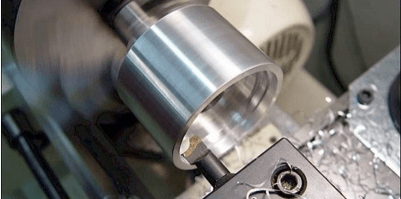
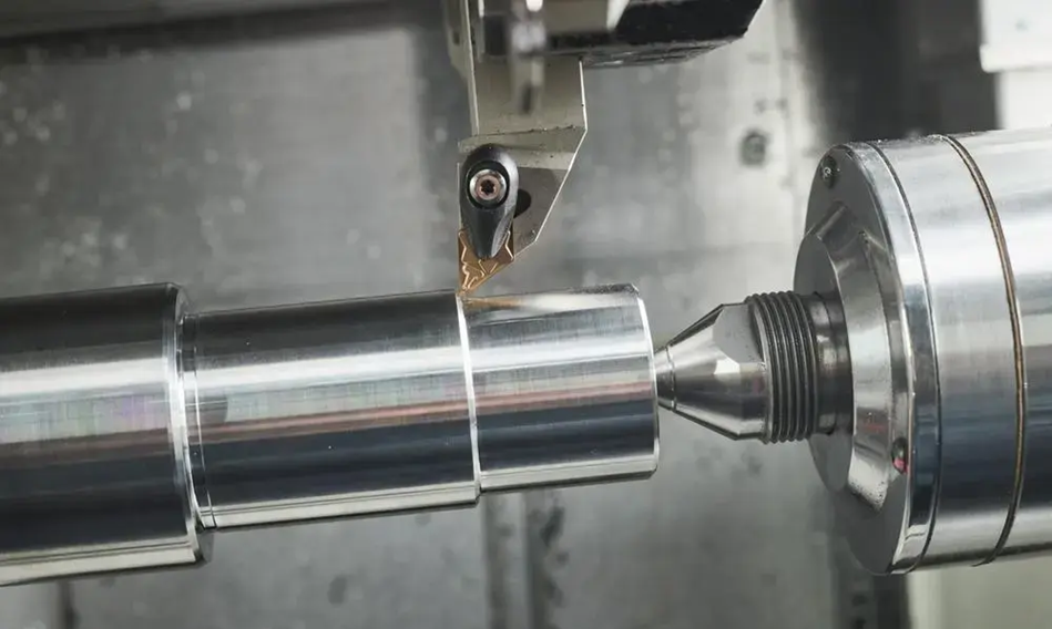
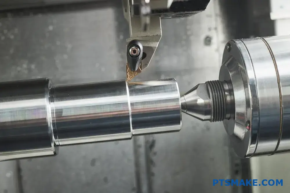
CNC Boring for Shaft Fitment Accuracy
Among the many machining operations involved in steering gear production, boring is perhaps the most critical. The rudder shaft passes directly through the bore of the tiller head or quadrant, and the quality of this interface determines how faithfully helm forces are transmitted to the rudder. A bore that is even slightly off-center or oversized can compromise alignment, introduce unwanted play, or accelerate wear. Precision boring, therefore, is fundamental to both performance and safety.
High Hole Accuracy in CNC Boring
Defining CNC Boring in Steering Applications
Boring is the process of enlarging and finishing an existing hole to a precise diameter and alignment. In the context of marine steering:
- The tiller head bore must clamp tightly onto the rudder stock without distortion.
- The quadrant bore must align perfectly with the rudder shaft, maintaining concentricity during rotation.
CNC boring machines use digital programming and rigid cutting tools to achieve accuracy beyond what manual machining can consistently provide. By following programmed tool paths, the bore diameter, roundness, and surface finish are held to exacting tolerances.
Why Precision Boring Matters for Shaft Alignment
The relationship between the rudder shaft and its connected components is critical. Even slight misalignment introduces mechanical inefficiencies that multiply under load. For example:
- Axial misalignment (shaft not parallel with bore) causes uneven load distribution, increasing wear on one side.
- Radial misalignment (shaft not centered in bore) leads to steering “tight spots” where movement is resisted.
- Excessive clearance between shaft and bore produces play, leading to lag in helm response.
Accurate boring ensures the shaft sits squarely, rotates freely, and transmits torque with minimal loss. This is why CNC boring is often considered the most important operation in steering gear manufacture.
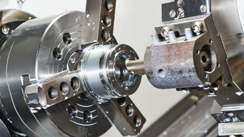
Shaft Design for Precision Machining
Surface Finish and Its Impact on Performance
Boring is not only about diameter but also about surface finish. Rough surfaces create friction and wear, while overly polished finishes may reduce the ability of lubricants to adhere. CNC boring allows manufacturers to achieve surface roughness values tailored to marine applications, typically in the range of Ra 0.8–1.6 µm.
This level of finish ensures:
- Smooth rotation without binding.
- Adequate retention of lubricating film.
- Reduced risk of galling between the bore and the shaft.
Such refinements make the difference between a steering system that feels stiff and one that feels seamless under hand.
The Role of Tolerances in Bore Fitment
Different types of shaft fits are specified depending on the application:
- Interference fits (slightly smaller bore than shaft) provide maximum grip, common in high-load quadrants.
- Transition fits (minimal clearance), balance grip, and removability are often used in tiller heads.
- Clearance fits (slightly larger bore than shaft) allow free movement where rotational play is acceptable, though rarely in steering.
CNC boring enables manufacturers to hold these fits to within ±0.01–0.02 mm. Achieving such tolerances ensures the bore grips correctly without overstressing the shaft or creating points of weakness.
Case Study: Misalignment and Its Consequences
In one documented case, a cast quadrant with a manually machined bore developed progressive misalignment. The initial clearance seemed acceptable during installation, but under load, the shaft shifted slightly within the bore. This led to:
- Increased steering resistance in one quadrant of rotation.
- Accelerated wear on the rudder stock surface.
- Loosening of keyways, eventually resulting in loss of helm control mid-passage.
The issue was traced back to a bore that was oversized by just 0.15 mm—seemingly insignificant but disastrous in practice. Had the quadrant been CNC-bored, such deviation would have been eliminated at the production stage.
Examples of Improved Performance Through CNC Boring
Yard reports and repair logs frequently highlight how replacing poorly machined components with CNC-bored parts improves steering:
- A racing yacht experiencing helm “slop” reduced play by 70% after installing CNC-bored tiller heads.
- A commercial vessel extended its steering gear service interval from 18 months to 36 months due to reduced wear at bore interfaces.
- Long-distance cruisers report smoother steering and less fatigue on passage after upgrading from cast quadrants to CNC-machined equivalents.
These examples underscore the real-world payoff of precision boring: not just improved feel, but measurable gains in reliability and service life.
CNC Boring vs. Traditional Methods
Manual boring and reaming have long been used in marine workshops, but they depend heavily on operator skill. Variability is inevitable, especially when performed on worn machines or under time pressure. By contrast, CNC boring:
- Eliminates human error by relying on digital precision.
- Ensures concentricity even in deep bores.
- Allows for custom adjustments across production runs.
The difference is not theoretical; it directly translates into steering reliability, especially under demanding sea conditions.
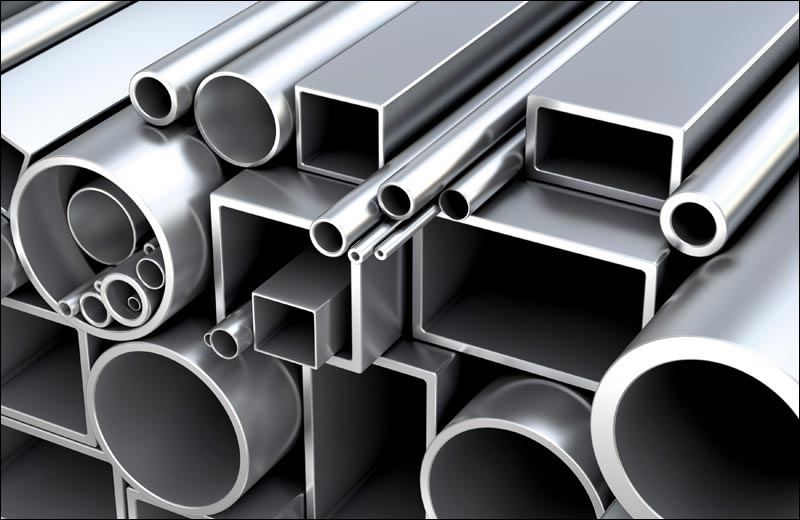
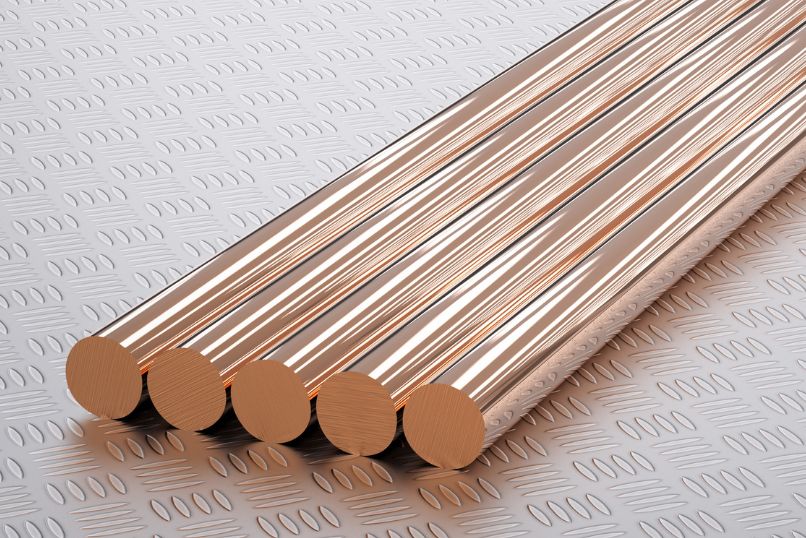
Material Selection: Aluminum Bronze vs. Stainless Steel
Beyond precision machining, the choice of material has a profound effect on how long steering components last and how well they perform. Tiller heads and quadrants operate in one of the harshest mechanical environments on a vessel: constantly loaded, exposed to saltwater, and subject to both cyclic stresses and corrosion. While design and tolerances define accuracy, material selection determines durability. Among the options available, aluminum bronze and stainless steel stand out as the two most widely used alloys. Understanding their differences is essential for selecting the right material for specific vessels and operating conditions.
Corrosion Resistance in Saltwater Environments
Saltwater is unforgiving. It accelerates galvanic corrosion, pits exposed metals, and exploits even the smallest surface imperfections. This makes corrosion resistance the first consideration in material selection.
- Aluminum Bronze contains copper, aluminum, and often nickel, forming a passive oxide layer that protects against seawater attack. It shows excellent resistance to biofouling, stress corrosion, and crevice corrosion.

- Stainless Steel (particularly marine grades like 316 or duplex) resists general corrosion but is more prone to localized pitting and crevice attack if oxygen is restricted, such as under deposits or seals.
In practice, aluminum bronze often performs better in continuously submerged conditions, while stainless steel requires careful selection of grade and protective maintenance to avoid localized breakdowns.
Mechanical Properties: Strength, Fatigue, and Wear
Steering gear components must withstand repetitive loading as the rudder constantly reacts to hydrodynamic forces. Material strength and fatigue resistance, therefore, play a central role.
- Aluminum Bronze: Offers excellent tensile strength (500–800 MPa) and remarkable fatigue resistance, making it ideal for parts under cyclic loads. Its toughness reduces the risk of brittle fracture.
- Stainless Steel: Provides high tensile strength (500–1000 MPa, depending on grade) and good hardness, which enhances resistance to surface wear. However, some grades are more notch-sensitive, increasing fatigue risk in poorly designed castings.
In real-world use, aluminum bronze tends to outperform in long-term cyclic applications, while stainless steel offers greater stiffness and resistance to deformation under peak loads.
Comparative Analysis: Pros and Cons of Each Alloy
Choosing between aluminum bronze and stainless steel involves weighing trade-offs rather than finding a universally superior option.
Aluminum Bronze
- Exceptional seawater corrosion resistance.
- High fatigue strength and toughness.
- Naturally anti-fouling due to copper content.
- Heavier than stainless steel at equal strength levels.
- More expensive in raw material cost.
Stainless Steel
- Widely available and cost-effective.
- High tensile strength and hardness.
- Easier to source in standardized grades.
- Susceptible to pitting and crevice corrosion.
- Certain grades require regular passivation or protective coatings.
For many high-performance or long-term applications, aluminum bronze is preferred despite its cost. Stainless steel, however, remains popular for production vessels where availability and cost efficiency are priorities.
Applications in Different Vessel Types
The choice of material often reflects vessel type, operating conditions, and owner priorities.
- Racing yachts: Frequently use aluminum bronze quadrants and tiller heads for maximum reliability under repeated high loads. The slight weight penalty is offset by reduced risk of failure.

- Commercial vessels: Often favor stainless steel due to cost and availability, especially where routine maintenance is already built into operations.
- Cruising yachts: May use either alloy, with aluminum bronze favored for bluewater cruising where durability is valued over cost.
- Military or offshore vessels: Typically specify aluminum bronze for critical steering systems, where failure is unacceptable and corrosion resistance is paramount.
These examples illustrate that while both alloys are viable, operational context is the decisive factor.
Real-World Examples of Performance
Case studies highlight the practical differences between the two materials:
- A fleet of coastal ferries operating in brackish water replaced stainless steel quadrants with aluminum bronze. Maintenance intervals doubled, and steering reliability improved markedly.
- A production yacht builder switched from aluminum bronze to 316 stainless steel for tiller heads to reduce costs. Within five years, owners reported localized pitting at shaft interfaces, requiring more frequent inspections.
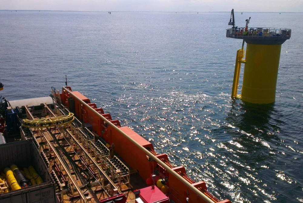
- Offshore oilfield service vessels use aluminum bronze almost exclusively for steering gear, citing its proven record of resisting both seawater corrosion and mechanical fatigue in 24/7 operations.
These real-world experiences reinforce the principle that steering material selection should never be driven by cost alone.
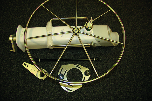
Failures Caused by Misaligned Cast Quadrants
Quadrants are central to wheel-steered vessels, transferring helm input from cables or hydraulic rams directly to the rudder stock. When manufactured by casting, quadrants often contain slight imperfections that may not be obvious during installation but later manifest as misalignment. Unlike CNC-machined parts, cast quadrants rely on molds and post-processing, which can introduce uneven geometry. Even a small deviation in bore angle or mounting face flatness can create significant long-term issues. Misaligned quadrants not only affect handling but can also trigger structural failures under cyclic steering loads.
Common Failure Modes in Cast Quadrants
When alignment errors exist, quadrants are exposed to forces they were not designed to carry. Over time, this leads to distinct failure modes:
- Cracking: Stress concentrates at thin sections, particularly around the hub and keyway.
- Deformation: Uneven loading bends arms or flanges, distorting cable tension.
- Accelerated wear: Cables or chains cut into grooves unevenly, deepening wear tracks.
- Slippage: Improper bore fit causes the quadrant to slip on the rudder shaft, disrupting helm response.
These failures may occur gradually, but they compromise safety long before catastrophic failure becomes visible.

Causes of Misalignment in Cast Components
The root causes of quadrant misalignment stem from the casting process itself and subsequent machining quality. Some of the most common include:
- Mold distortion: Slight warping of molds during cooling produces out-of-round bores.
- Inconsistent shrinkage: Differential cooling rates create uneven wall thickness.
- Machining inaccuracies: Manual drilling or reaming fails to correct casting imperfections.
- Poor installation practices: Misaligned keyways or uneven clamping further amplify manufacturing flaws.
Each of these introduces geometric inaccuracies that compound over time, particularly when steering systems are under high loads.
Mechanical Consequences of Misalignment
Once a cast quadrant is misaligned, the steering system begins to operate outside its designed geometry. This creates knock-on effects across the assembly:
- Steering resistance increases, making the helm feel heavy or jerky.
- Load imbalance develops between port and starboard turns, causing asymmetric handling.
- Shaft wear accelerates, as side-loading introduces micro-movements between bore and shaft.
- Cable tension fluctuates, leading to uneven stretch and premature cable replacement.
These consequences gradually erode steering precision and reliability, often without immediate warning signs.
Documented Incidents and Failures
Marine accident reports and yard records provide clear evidence of failures linked to cast quadrant misalignment:
- Case 1 – Coastal cruiser: A 38-foot yacht suffered a complete loss of steering mid-channel. Post-incident inspection revealed a cracked cast quadrant hub caused by long-term misalignment stress.
- Case 2 – Charter vessel: Steering became increasingly stiff after just two seasons. Investigation found uneven cable wear where the quadrant arms had deformed, altering groove alignment.
- Case 3 – Racing yacht: A cast quadrant slipped on its rudder stock during heavy seas. The bore was found oversized by 0.2 mm, allowing movement under peak load.
These examples demonstrate that seemingly minor misalignments often lead to serious, costly, and dangerous outcomes.
How CNC Machining Reduces the Risk
CNC machining addresses the root problems of casting by delivering precise geometry and eliminating variability. Advantages include:
- Concentric bores: CNC boring ensures the shaft and quadrant hub align perfectly.
- Flat mounting faces: Milling operations guarantee even load transfer to the shaft collar.
- Consistent groove spacing: Steering cables or chains run evenly, preventing asymmetric wear.
- Repeatability: Every component produced matches the specification, removing the uncertainty of casting.
By replacing cast quadrants with CNC-machined equivalents, the probability of misalignment-related failures is dramatically reduced.
Why Failures Are More Critical in Steering Systems
Unlike other mechanical failures onboard, quadrant failure directly compromises control of the vessel. Key differences make steering component failures uniquely hazardous:
- No redundancy: Most yachts and small commercial vessels have a single steering system.
- Immediate impact: Loss of steering disables maneuverability within seconds.
- High stress environment: Heavy weather amplifies the effects of any misalignment or weakness.
This explains why professional yards and classification societies increasingly discourage the use of unverified cast quadrants in favor of CNC-machined designs.
Benefits of CNC-Crafted Steering Components
In modern marine engineering, the shift from traditional cast or manually machined components to CNC-crafted tiller heads and quadrants has transformed steering reliability. CNC machining delivers not only precision but also consistency across all units, ensuring every vessel equipped with such components experiences predictable, high-quality performance. The benefits span mechanical reliability, operational efficiency, and long-term cost-effectiveness, making CNC-crafted steering gear the preferred choice for professional and recreational mariners alike.
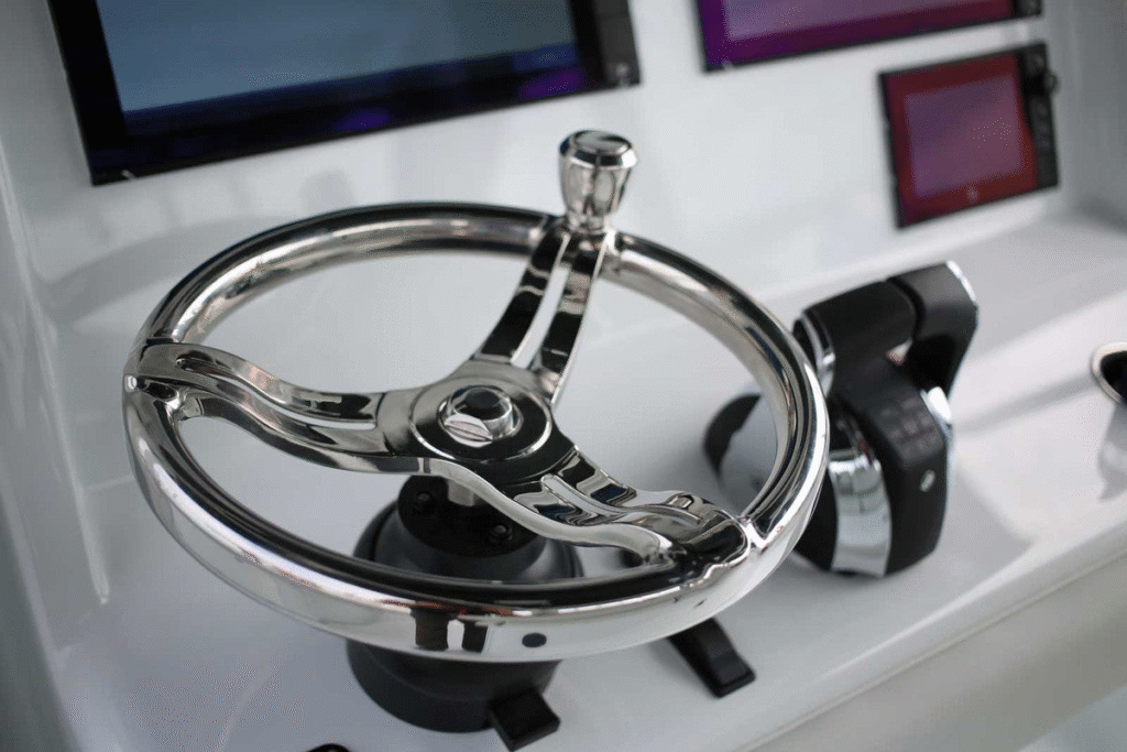
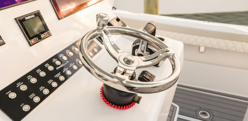
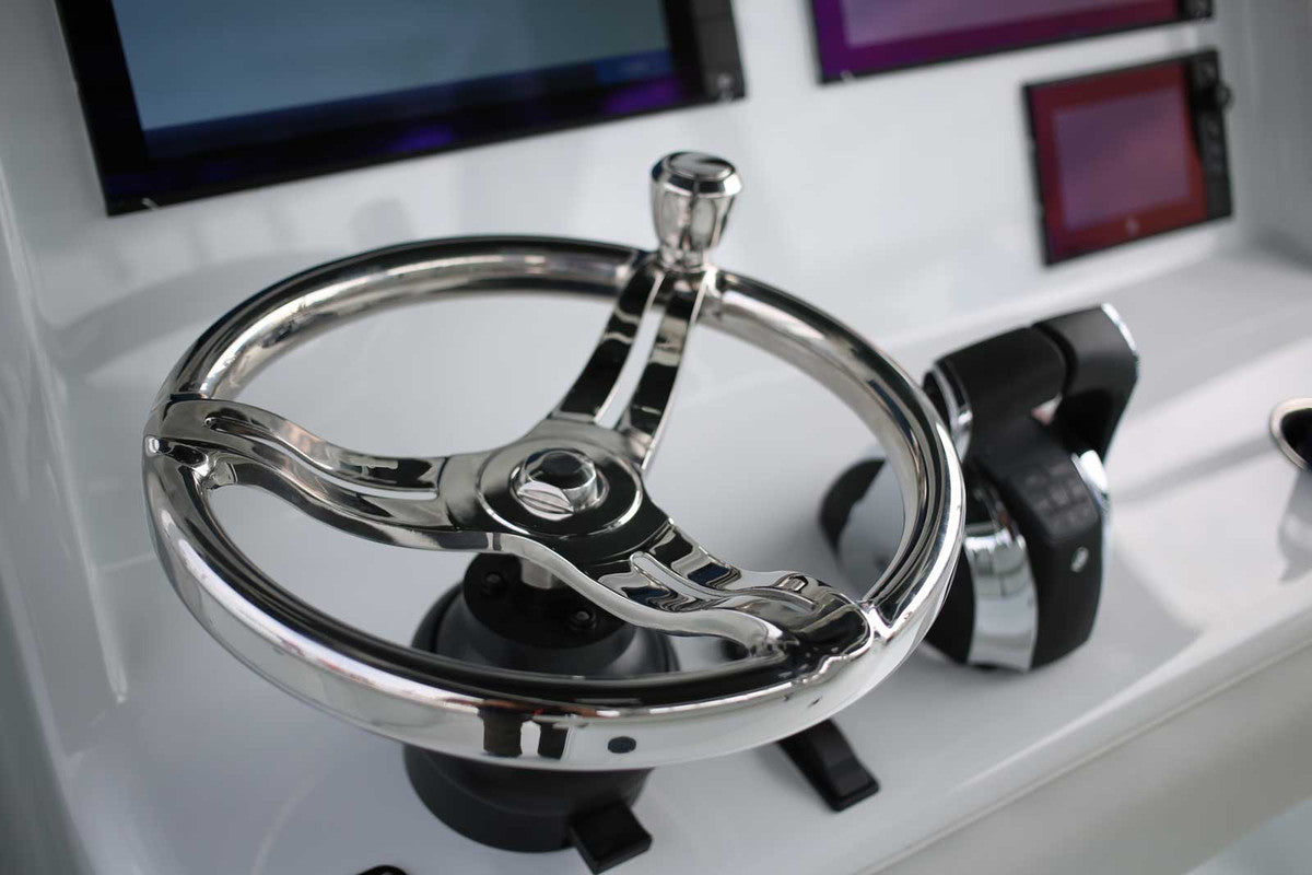
Boat Sport Steering Wheel with Knob
Increased Reliability and Lifespan
The most immediate benefit of CNC-manufactured components is their superior reliability. Every bore, pivot, and surface is machined to tight tolerances, ensuring parts fit perfectly from the start. This precision reduces stress concentrations and uneven loading that commonly plague cast components.
- Consistent performance: Each part behaves identically, avoiding surprises during installation or operation.
- Extended service life: Reduced friction, wear, and misalignment translate to years of reliable steering.
- Minimized failures: Precision eliminates the common causes of cracking, deformation, and slippage found in cast components.
Vessels equipped with CNC-machined steering gear can expect fewer unscheduled repairs, enhancing both safety and operational continuity.
Reduced Maintenance and Downtime
Beyond reliability, CNC components lower the ongoing cost of ownership. Properly machined tiller heads and quadrants require less frequent inspection and adjustment.
- Easier installation: Perfectly aligned bores and mounting faces reduce assembly errors.
- Stable cable and shaft alignment: Wear on associated hardware slows, lowering replacement frequency.
- Lower labor costs: Less maintenance time is required for routine inspections, freeing crews for other tasks.
Over a vessel’s lifetime, these savings often outweigh the initial investment in CNC components.
Enhanced Steering Performance and Safety
Performance gains are also significant. CNC-machined components transmit helm input more accurately, providing immediate and precise response at the rudder.
- Direct helm feel: No lag or play between input and rudder movement.
- Smooth operation: Tight tolerances eliminate binding, creating effortless control even under load.
- Predictable handling in rough conditions: Critical for maneuvering in tight harbors, strong currents, or heavy seas.
Enhanced performance also means increased safety. Mariners can react quickly and confidently, reducing the likelihood of accidents caused by delayed or inconsistent steering responses.
Return on Investment for Professional-Grade Marine Applications
While CNC machining may increase upfront costs, the long-term benefits justify the investment:
- Reduced part replacement frequency lowers overall maintenance budgets.
- Minimized downtime increases vessel availability, critical for commercial operations.
- Improved vessel value: High-quality steering components contribute to resale value and reputation for seaworthiness.
For professional mariners, racing yachts, or serious cruisers, CNC-crafted steering gear represents a clear advantage in both operational efficiency and peace of mind.
Consistent Quality Across Production Runs
CNC machining ensures that every tiller head or quadrant produced matches exact specifications, regardless of batch size or production volume. This consistency eliminates variability often seen with cast or manually machined parts.
- Uniform performance: Every component behaves the same, simplifying installation and maintenance.
- Predictable system behavior: Operators can rely on consistent helm response across multiple vessels or replacements.
Ability to Produce Complex Geometries
CNC technology allows the creation of shapes and features that are difficult or impossible with traditional casting or manual methods. This capability enables optimized component designs that enhance strength, reduce weight, and improve hydraulic or cable routing.
- Optimized load distribution: Complex profiles reduce stress concentrations and extend part life.
- Weight reduction: Carefully designed geometry can lower mass without sacrificing strength.
- Improved efficiency: Cable grooves, keyways, and pivot surfaces can be precisely tailored for smoother steering operation.
Conclusion
Precision and reliability in marine steering systems are not optional; they are essential. Tiller heads and quadrants, though compact components, bear the full responsibility of translating helm input into accurate rudder movement. Any imperfection, misalignment, or material weakness can have immediate consequences for both performance and safety. As vessels face variable loads, corrosive environments, and continuous operation, the benefits of high-quality engineering become undeniable. CNC machining, combined with careful material selection, addresses these challenges, offering sailors confidence that their steering system will perform flawlessly under all conditions.
Key Takeaways on CNC Precision
CNC-crafted components deliver consistent tolerances that manual methods cannot match. Key points include:
- Exact bore alignment and concentricity for flawless shaft rotation.
- Uniform pivot surfaces to reduce friction and wear.
- Repeatable geometry across all units, eliminating variability between parts.
These features directly improve steering response, minimize maintenance, and extend service life.
Importance of Material Selection
Equally important is selecting the right alloy for the environment and vessel type:
- Aluminum bronze provides superior corrosion resistance, fatigue strength, and long-term durability, ideal for high-performance or offshore applications.
- Stainless steel remains a reliable choice for production and commercial vessels, provided proper maintenance and protective measures are applied.
Considering both material and machining quality ensures that the steering system not only functions accurately but also withstands the harshest marine conditions.
Modern CNC technology has transformed tiller heads and quadrants from potential points of failure into robust, dependable components. Investing in CNC-crafted steering gear, along with appropriate material selection, is not merely an upgrade; it is a critical decision that safeguards performance, safety, and peace of mind at sea. Every mariner who prioritizes precision, longevity, and reliability in their vessel’s steering system will appreciate the tangible benefits of this advanced engineering approach.

