

Deep pocket milling is one of the most demanding operations in modern machining. It involves removing material from cavities that are significantly deeper than their width, often requiring long-reach cutters and precise toolpath control. Industries such as aerospace, mold-making, and energy rely heavily on this process to create structural pockets, cooling channels, and housing features that demand both accuracy and surface integrity. Despite advancements in tooling and machine stability, deep-pocket milling continues to test even experienced machinists due to its complex chip evacuation dynamics.
Efficient chip evacuation plays a central role in achieving stable and productive deep-pocket operations. When chips are not removed effectively, they tend to recirculate within the cavity, increasing cutting forces and heat accumulation. This leads to poor surface finishes, accelerated tool wear, and even catastrophic tool failure. In contrast, maintaining a clean cutting zone enhances tool life, promotes consistent surface quality, and allows for higher feed and speed settings. For shops striving to improve cycle times and minimize rework, understanding and managing chip flow is as critical as selecting the right toolpath or spindle speed.
This article explores the challenges of chip evacuation in deep-pocket milling and presents practical solutions that machinists and process engineers can apply on the shop floor. It explains how chip formation behavior, tool geometry, coolant delivery, and cutting strategies interact in confined spaces. Through real-world insights and best practices, the goal is to help readers not only recognize the early signs of evacuation issues but also adopt proven techniques that keep chips under control while maintaining precision and efficiency.
Understanding Chip Formation in Deep Pocket Milling
Efficient chip evacuation starts with understanding how chips are generated and behave during cutting. In deep pocket milling, the interaction between tool geometry, material properties, and machining parameters becomes more complex due to the confined cutting zone. Chips tend to curl and accumulate within narrow cavities, disrupting both tool stability and coolant flow. Unlike open-face milling, where chips are quickly dispersed, deep-pocket operations restrict chip movement, increasing the risk of recutting and tool damage.
How Chips Are Generated During Milling
Chips are formed as the cutting edge shears material from the workpiece. During this process, high stress and temperature concentrate along the shear zone, forcing the material to deform plastically and separate from the bulk. The nature of this deformation determines the type and shape of the chip. In deep pockets, the cutting edge operates under limited chip escape space, so the generated chips are more likely to compact or adhere to the tool surface.
The shearing process is influenced by several factors:
- Cutting speed and feed rate: Higher cutting speeds produce thinner, more continuous chips, while lower speeds or high feed rates tend to create thicker segments.
- Tool geometry: The rake angle and helix angle affect how smoothly chips curl and break. A positive rake angle promotes easier shearing but can weaken tool edges during long-reach cuts.
- Workpiece temperature: Increased heat softens the material, changing chip flow behavior and potentially causing adhesion on the cutting edge.
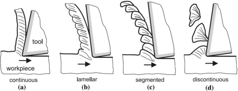
Types of Chips and Their Characteristics
Chip formation varies depending on the material’s ductility and the cutting conditions. Understanding these chip types helps in predicting evacuation performance.
- Continuous chips: Formed in ductile materials such as aluminum or mild steel under stable conditions. While they offer a smooth cut, they can easily entangle within deep pockets, blocking coolant paths.
- Segmented or serrated chips: Common in harder alloys like titanium or stainless steel. Their broken structure improves evacuation but generates more vibration and tool wear.
- Discontinuous chips: Typically appear when cutting brittle materials such as cast iron. These chips are easier to remove but can produce irregular surface finishes if not controlled.
Each chip type interacts differently with pocket geometry. Continuous chips require aggressive evacuation support, while segmented chips rely on controlled cutting parameters to avoid excessive heat buildup.
Influence of Material, Feed Rate, and Cutting Speed
The combination of cutting parameters and material behavior dictates chip formation efficiency. For example, in aluminum, increasing spindle speed often improves chip flow due to the material’s low hardness and high ductility. In contrast, titanium alloys require balanced speed and feed settings to prevent long, stringy chips that resist evacuation. Feed per tooth directly affects chip thickness, while cutting speed governs thermal softening and tool, chip friction.
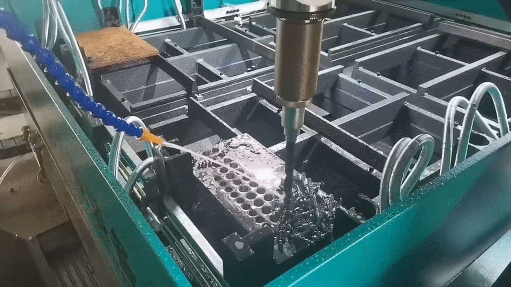
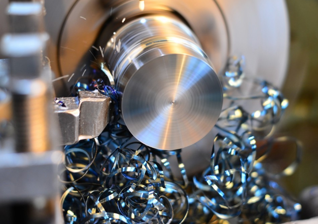
Chip Removal Performance on CNC Drilling Machines
Optimizing these parameters ensures chips are neither too thin to fragment nor too thick to compact within the pocket. Finding this balance often involves experimental tuning and real-time observation of chip color, length, and curl behavior.
Role of Pocket Depth and Geometry in Chip Accumulation
Pocket depth significantly impacts how chips behave during milling. As the cavity gets deeper, chips must travel farther to exit the cutting zone. Narrow walls and sharp corners create turbulence that traps chips, while poor coolant access worsens the problem. Even small design features, such as corner radii and pocket bottom angles, influence chip movement.
To minimize accumulation:
- Maintain gradual wall transitions where possible.
- Design toolpaths that periodically clear chips from the pocket.
- Use extended flutes only when required, as longer tools increase vibration and restrict coolant reach.
A thorough understanding of chip formation mechanics forms the foundation for addressing evacuation problems. Once machinists recognize how material properties, tool geometry, and pocket design interact, they can make informed adjustments that improve both cutting stability and overall machining performance.
Common Challenges in Chip Evacuation
Deep pocket milling introduces several complications that directly affect productivity and part quality. As chips accumulate in confined spaces, they disrupt cutting efficiency and lead to secondary defects that often go unnoticed until inspection. The main challenges include clogging, surface damage, and heat buildup. Each of these issues stems from poor chip control and insufficient removal methods, and together they can drastically shorten tool life and compromise dimensional accuracy.
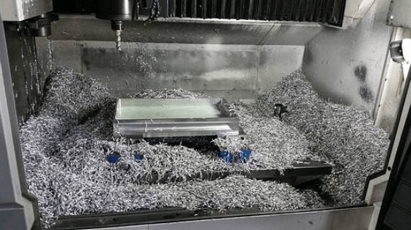
Milling Chip Evacuation Tactics
Chip Clogging
Chip clogging is the most frequent problem encountered in deep-pocket milling. When the cutting zone becomes saturated with chips, they restrict the tool’s cutting edge from engaging the material cleanly. Instead of being expelled, chips remain trapped between the tool flutes and the cavity walls, creating friction and unstable cutting forces.
Several factors contribute to chip clogging:
- Insufficient flute space: Tools with a high flute count have smaller gullets, reducing chip-carrying capacity. This leads to faster accumulation when machining deep pockets.
- Inadequate coolant flow: Without strong coolant pressure or air assistance, chips remain inside the pocket, where they compact into dense clusters.
- Improper tool path design: Aggressive stepdowns or high engagement angles generate large chip volumes faster than the evacuation system can handle.
Clogging leads to increased spindle load, reduced cutting accuracy, and sometimes complete tool breakage. Preventing this requires a combination of optimized tool geometry, controlled material removal rate, and efficient flushing methods.
Surface Damage and Poor Finish
Once chips fail to leave the cutting area, they begin to interfere with the tool’s motion and the freshly machined surface. Recutting occurs when trapped chips are forced under the cutting edge again, scratching or gouging the surface. This effect is especially problematic in precision components that demand tight surface finish tolerances.
Common consequences of poor chip evacuation on surface integrity include:
- Micro-scratches and gouges: Hard chips dragged across the part leave visible defects that often require rework.
- Built-up edge formation: When chips adhere to the cutting edge due to high temperature, the tool’s effective geometry changes, producing rough finishes.
- Dimensional deviations: The recutting action alters cutting pressure, slightly deflecting the tool and creating uneven walls or bottom surfaces.
Maintaining a smooth surface depends on consistent chip flow. Using cutters with polished flutes, applying suitable coatings, and employing programmed retracts between passes can minimize the chances of recontact between chips and the machined surface.
Heat Accumulation and Reduced Tool Life
Deep pockets limit coolant access, which increases the temperature in the cutting zone. Chips act as heat carriers, but when they remain trapped, they instead insulate the area and raise thermal loads on the tool. Excessive heat accelerates wear mechanisms such as oxidation, diffusion, and coating breakdown.
Typical indicators of heat-related problems include:
- Discoloration on the tool edges indicates overheating.
- Rapid flank wear caused by prolonged exposure to hot chips.
- Plastic deformation of the tool tip in high-temperature materials like titanium or Inconel.
To reduce heat accumulation, machinists can adopt high-pressure coolant delivery, maintain lower radial engagement, and shorten continuous cutting intervals. Periodic retraction cycles and air-blast cooling also help dissipate trapped heat, preventing thermal distortion in both the tool and workpiece.
Addressing these common challenges requires a systematic approach. Understanding the causes behind chip clogging, surface damage, and heat buildup allows machinists to tailor their strategies for each material and pocket geometry. A balanced combination of tool design, coolant management, and path optimization can transform deep-pocket milling from a high-risk task into a stable and efficient process.
Factors Affecting Chip Evacuation
The efficiency of chip evacuation in deep-pocket milling depends on how multiple factors interact during cutting. Each variable, from pocket geometry to material type, plays a role in determining how easily chips can move away from the cutting zone. When one of these elements is poorly optimized, the entire process becomes unstable, resulting in excessive tool wear, inconsistent surface finishes, and frequent interruptions. Understanding these influences allows machinists to design more reliable and predictable cutting setups.
Pocket Geometry and Design
The geometry of the pocket directly controls chip flow behavior. Deep, narrow cavities restrict the natural movement of chips, while sharp internal corners trap debris that coolant cannot easily reach. The more confined the space, the greater the chance of recutting and clogging.
A few geometric aspects that influence evacuation include:
- Depth-to-width ratio: When depth greatly exceeds width, chips must travel farther to exit, increasing compaction risk.
- Corner radii: Tight corners hinder coolant circulation and cause chip accumulation at the edges. Rounded radii promote smoother flow and prevent buildup.
- Wall inclination: Slightly tapered walls can encourage chips to slide upward instead of settling at the bottom of the cavity.
Effective design planning, even at the CAD stage, can significantly improve machining performance. Introducing relief pockets, exit channels, or staged machining depths reduces internal turbulence and allows chips to leave the cavity more efficiently.
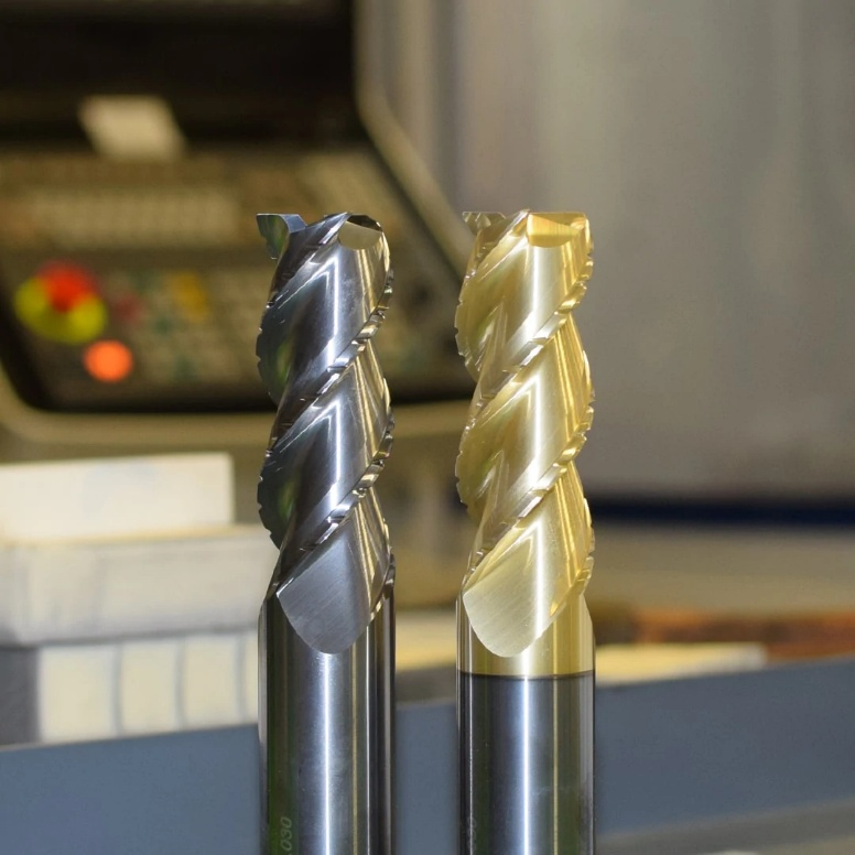
Tool Design and Geometry
Tool geometry determines how chips are cut, curled, and ejected. In deep pocket milling, where the cutting edge often operates in limited space, the flute shape and helix angle become especially critical. A mismatch between tool geometry and pocket design can cause chips to compact rather than clear.
Key tool design considerations include:
- Flute number and gullet size: Fewer flutes provide larger gullets that improve chip capacity, while high flute counts are better suited for finishing but may increase clogging risk.
- Helix angle: A high helix angle helps lift chips upward, reducing heat and friction. However, too high an angle can decrease tool rigidity in long-reach cutters.
- Chipbreaker and polished flutes: These features break long chips into smaller segments and reduce adhesion, particularly useful when cutting sticky materials like aluminum or copper.
- Tool coating and surface finish: Coatings such as TiAlN, DLC, or ZrN reduce chip adhesion and improve wear resistance, especially under high-temperature conditions.
Balancing these design elements ensures chips are formed cleanly and guided efficiently toward the pocket opening.
Cutting Parameters
Cutting speed, feed rate, and depth of cut directly influence chip shape and evacuation behavior. Incorrect combinations create unstable chip formation that either fragments excessively or forms long curls that entangle within the pocket.
- Feed rate: Higher feed per tooth increases chip thickness and enhances the chance of self-evacuation. However, excessive feed can overload the tool, while too low a feed leads to rubbing and built-up edges.
- Cutting speed: Increasing spindle speed can generate thinner, more fluid chips, but also raises cutting temperature. The optimal range depends on material conductivity and tool coating.
- Depth of cut: Shallow axial passes minimize chip load per revolution and allow better coolant penetration. Deep axial engagement may require intermediate retracts to prevent chip packing.
Proper parameter tuning involves a balance between chip formation efficiency and thermal stability. Monitoring spindle load and tool wear helps identify whether the parameters are optimized.
Material Properties
The material being machined largely dictates chip morphology. Ductile metals like aluminum and mild steel tend to produce long, continuous chips that require aggressive evacuation methods, while brittle materials like cast iron form short, broken chips that clear easily but can cause abrasive wear.
Important material-related aspects include:
- Thermal conductivity: Materials with poor conductivity, such as titanium and Inconel, retain heat in the cutting zone, making chip evacuation critical to prevent thermal damage.
- Work hardening behavior: Alloys that harden during cutting produce tougher chips that resist breaking and may adhere to the tool.
- Elastic modulus and ductility: Highly ductile materials produce curled, stringy chips that demand tools with effective chipbreaker designs and strong air or coolant flushing.
Selecting suitable cutting fluids, coatings, and tool geometries based on material type can significantly enhance chip evacuation.
Solutions to Chip Evacuation Problems
Deep pocket milling requires more than just selecting the right tool and parameters. Successful chip evacuation comes from combining multiple techniques that complement each other: coolant strategy, tool path design, cutter geometry, and real-time process adjustments. Each method addresses a specific problem, and when applied together, they significantly enhance machining stability, surface quality, and tool life.
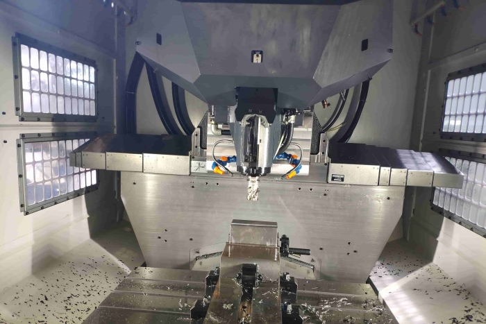
Chip Management & Breakage in the CNC Machining Process
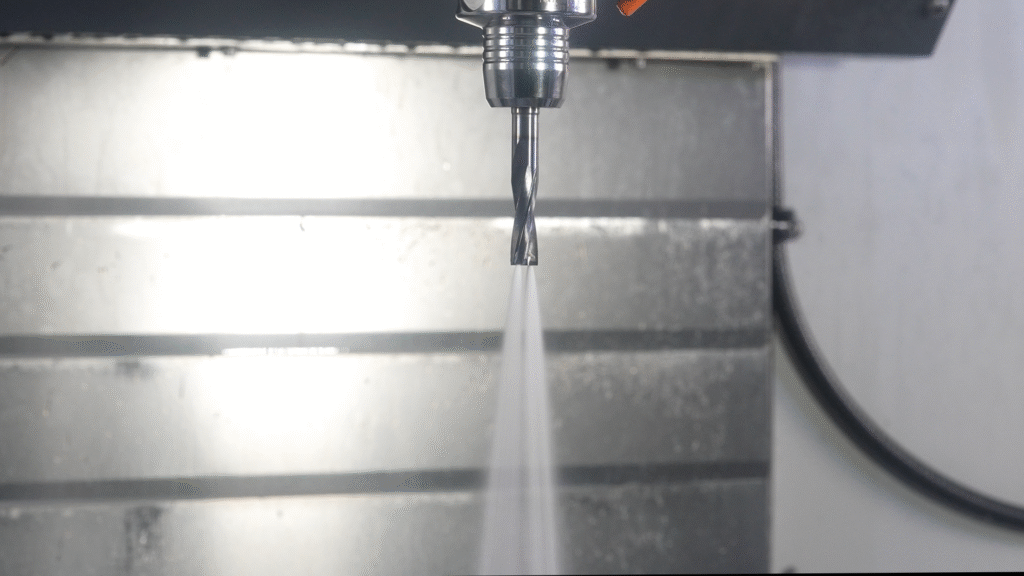
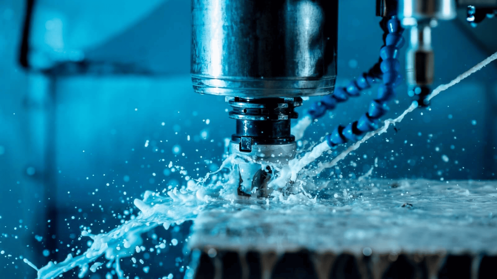
High-Pressure Coolant Systems
Coolant is the most direct and effective method for controlling chips in deep cavities. In conventional setups, coolant flow often fails to reach the cutting zone, especially when the pocket is narrow or deep. High-pressure systems solve this issue by forcing coolant through the tool or specialized nozzles, ensuring chips are flushed out before they accumulate.
Key benefits of high-pressure coolant include:
- Efficient chip evacuation: The strong jet dislodges chips from the cavity and prevents them from settling at the bottom.
- Temperature control: By carrying heat away from the tool and workpiece, coolant minimizes thermal deformation and extends tool life.
- Improved surface finish: Consistent flushing reduces chip recontact, leading to smoother surface textures.
Recommended pressure levels depend on the operation and tool type. For most deep-pocket milling operations, coolant pressures between 50 and 100 bar are effective. However, in hard-to-machine materials such as titanium, pressures above 150 bar may be required to maintain stable chip flow. Regular inspection of coolant lines and filters ensures uninterrupted flow and prevents foam or debris buildup that could weaken pressure delivery.
Optimized Tool Paths
Even with ideal coolant and tooling, poor tool path design can trap chips within the cavity. Traditional linear or zigzag passes tend to push chips into corners where coolant cannot reach. Optimized tool paths focus on maintaining consistent cutter engagement and promoting natural chip evacuation throughout the machining process.
Effective tool path strategies include:
- Trochoidal milling: This method uses circular tool motion with controlled stepovers to reduce radial engagement and create open paths for chip flow.
- Helical interpolation: Ideal for deep pockets and bores, this technique gradually removes material in a spiral, allowing chips to escape upward.
- Adaptive clearing: CAM software can generate dynamic tool paths that maintain constant chip load while optimizing evacuation angles.
Simulation tools in modern CAM systems can visualize chip flow and detect regions where chips might accumulate. Adjusting retract heights, entry angles, and re-cutting patterns in these simulations ensures cleaner pockets before the first toolpath is executed on the machine.
Tool Selection and Chip Breakers
Tool geometry plays a decisive role in managing chip shape and flow. Choosing tools that generate shorter, segmented chips helps prevent clogging and excessive heat buildup. Specialized chipbreaker features on the flute face interrupt chip formation, dividing long strands into manageable pieces.
When selecting a tool for deep pocket milling, consider:
- Flute geometry: Wide flutes and deep gullets increase chip space and promote faster evacuation.
- Chipbreaker designs: Tools with built-in chip splitters are effective for ductile materials that tend to produce long, continuous chips.
- Coatings and surface treatment: Coatings such as TiAlN or DLC reduce chip adhesion and friction, allowing chips to slide smoothly along the flute.
- Tool length and rigidity: Use the shortest possible tool extension to maintain stability and minimize vibration, which can otherwise disturb chip evacuation.
Additionally, different materials respond better to specific geometries. For example, aluminum alloys benefit from high-helix cutters with polished flutes, while stainless steel often requires chipbreaker-equipped end mills to manage heat and stringy chips.
Additional Practices for Enhanced Chip Evacuation
Beyond coolant and tool geometry, several secondary practices can improve chip evacuation efficiency. These methods focus on maintaining clean cutting conditions and ensuring the machine continuously operates under stable conditions.
- Air blast and vacuum systems: Air jets or vacuum-assisted systems remove chips without introducing liquid coolant, useful in dry or semi-dry machining setups.
- Periodic retract cycles: Short retraction movements at set intervals clear chips from the cutting area, especially in deep slots and cavities.
- Real-time monitoring: Using spindle load data, temperature sensors, or acoustic signals helps detect when chips start to pack inside the pocket.
- Tool wear inspection: Worn flutes or dull cutting edges worsen chip flow. Regular inspection and re-sharpening maintain effective evacuation performance.
In high-value parts, integrating these methods together produces the most consistent results. A strong coolant system, intelligent toolpath design, and well-chosen cutter geometry create a synergistic effect that minimizes chip buildup. Continuous monitoring and adaptive control further stabilize the process, making deep pocket milling both predictable and efficient.
By addressing chip evacuation from multiple angles, manufacturers can achieve higher productivity, lower scrap rates, and longer tool life even when machining complex pocket geometries or difficult materials.
Best Practices for Efficient Chip Evacuation
Maintaining reliable chip evacuation in deep pocket milling requires a coordinated approach that integrates planning, tool selection, and consistent monitoring. Even the most advanced equipment cannot compensate for poor preparation or improper setup. Successful machinists and process engineers apply a set of preventive and operational strategies that ensure chips are removed as quickly as they are generated.
Plan Pocket Geometry and Tool Selection Together
Effective chip control starts before the first cut. The geometry of the pocket and the type of tool used should be evaluated as a pair rather than separately. Poor alignment between pocket design and tool reach often creates unreachable corners or narrow zones where chips collect.
Key planning considerations include:
- Pocket design: Where possible, use gradual slopes, radiused corners, and open entry points to allow chip flow. Sharp corners or abrupt depth transitions limit coolant access and cause stagnation.
- Tool reach and rigidity: Select the shortest possible tool extension to reduce vibration. Extended tools are necessary for deep features, but excessive length amplifies deflection and makes evacuation less effective.
- Flute configuration: Choose a flute count and helix angle appropriate for the material and chip volume. For example, two- or three-flute end mills often perform better in aluminum because of their larger chip space.
Careful matching of pocket geometry and tool characteristics ensures that chips follow predictable paths instead of compacting within restricted areas.
Set Appropriate Feeds and Speeds
Chip formation is highly sensitive to cutting parameters. Incorrect settings not only affect surface quality but also determine whether chips are short enough to be cleared or long enough to entangle. Finding the right balance between cutting speed and feed per tooth is crucial.
- Feed rate: Increasing the feed slightly encourages thicker, more stable chips that carry heat away. However, excessive feed overloads the cutter and raises cutting forces.
- Cutting speed: Faster spindle speeds produce thinner, more flexible chips that can sometimes stick to the tool. Reducing speed in small increments may promote cleaner chip flow.
- Depth of cut: Break long machining passes into smaller stepdowns to give coolant better access and avoid compacted chip piles at the bottom of the cavity.
A well-tuned set of parameters maintains chip thickness within a manageable range, improving both evacuation and tool life. Periodic adjustments during production help adapt to tool wear and material variation.
Combine Coolant, Tool Path, and Chipbreaker Solutions
No single method can ensure clean chip evacuation. The best performance comes from integrating multiple strategies that complement one another. Coolant, tool geometry, and tool path design should all contribute to maintaining a continuous clearing flow.
- Coolant system: Use through-spindle or high-pressure delivery to reach the deepest areas of the pocket. Check for clogging in filters and nozzles regularly.
- Tool path optimization: Employ trochoidal or helical strategies that minimize full-width cuts and keep chips moving upward rather than sideways.
- Chipbreaker geometry: Choose tools designed for the specific material. For example, stainless steel requires strong chipbreakers, while aluminum benefits from smooth, polished flutes.
Coordinating these elements transforms deep pocket milling from a reactive process into a controlled, predictable one where chip flow is sustained throughout the cut.
Regular Monitoring and Maintenance
Even with an optimized setup, chip evacuation performance can degrade over time if maintenance is neglected. Coolant pressure may drop, tool edges can dull, and filters can clog—all of which interfere with chip movement.
To maintain consistency:
- Inspect tools: Replace or regrind when signs of wear, built-up edge, or coating damage appear.
- Check coolant systems: Ensure pressure and flow rates remain stable. Clean filters and tanks periodically.
- Monitor chip behavior: Observe chip color and length during cutting. Long, discolored, or welded chips indicate poor evacuation or excessive heat.
- Record data: Use spindle load monitoring or acoustic sensors to track when the process deviates from normal behavior.
Routine monitoring prevents downtime and protects both the tool and the workpiece. Over time, these small checks lead to a more efficient and repeatable machining process.
Adhering to these best practices builds a strong foundation for stable deep-pocket milling. Consistent planning, balanced parameters, and proactive maintenance together ensure that chips are removed effectively, preserving tool life and delivering superior surface quality with minimal interruptions.
Conclusion
Deep pocket milling presents one of the most persistent challenges in modern machining because chip evacuation becomes increasingly difficult as cavity depth grows. When chips fail to clear properly, they cause heat buildup, tool wear, and surface defects that compromise both accuracy and efficiency. Understanding the physics of chip formation, the influence of geometry, and the impact of cutting parameters allows machinists to identify the root causes of these problems before they escalate. Recognizing early warning signs such as discoloration, spindle load spikes, or poor surface finishes helps prevent costly rework and downtime.
Consistent chip evacuation depends on combining several strategies rather than relying on a single solution. High-pressure coolant delivery, optimized tool paths, and well-designed flute geometries work best when integrated together. Planning pocket geometry, setting balanced feeds and speeds, and maintaining equipment regularly complete the cycle of control. With these practices in place, deep-pocket milling shifts from a high-risk operation to a predictable, efficient process that delivers better surface finishes, longer tool life, and stable productivity.
