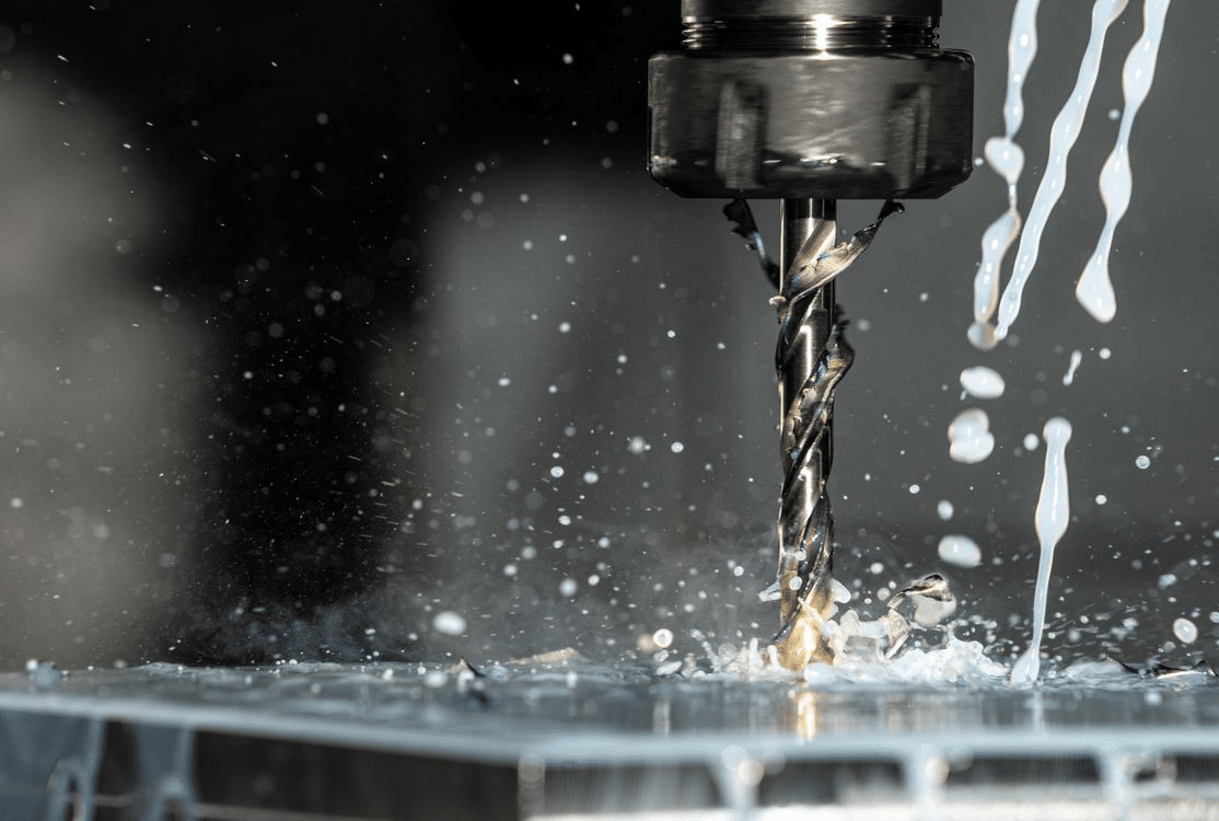
Design for Manufacturability in CNC machining is about shaping a part so it can be produced efficiently without compromising function. When a component is designed with the machining process in mind, it becomes easier to cut, easier to hold, and easier to inspect. This reduces long machining cycles, tool stress, and avoidable rework. It also helps achieve a cleaner surface finish and more predictable dimensional accuracy.
Good DFM practices reduce cost because they eliminate unnecessary complexity, oversized tolerances, and geometric features that demand special tools. They also minimize scrap by preventing weak walls, deep cuts, and difficult tool paths that cause vibration or deflection. In this article, I focus on practical geometry, tolerance, and feature-level guidelines that help designers and engineers create CNC-machined parts that are simpler to manufacture, more stable during cutting, and more consistent in quality.
Choose Geometries That Are Easy to Machine
The geometry of a part has a direct effect on cycle time, tool access, and surface quality. When shapes are straightforward and cutter-friendly, the machining process becomes smoother and more predictable. Parts with clean profiles, consistent radii, and accessible faces allow tools to remove material with less vibration and fewer tool changes. This results in better finishes, tighter dimensional control, and shorter overall machining time.

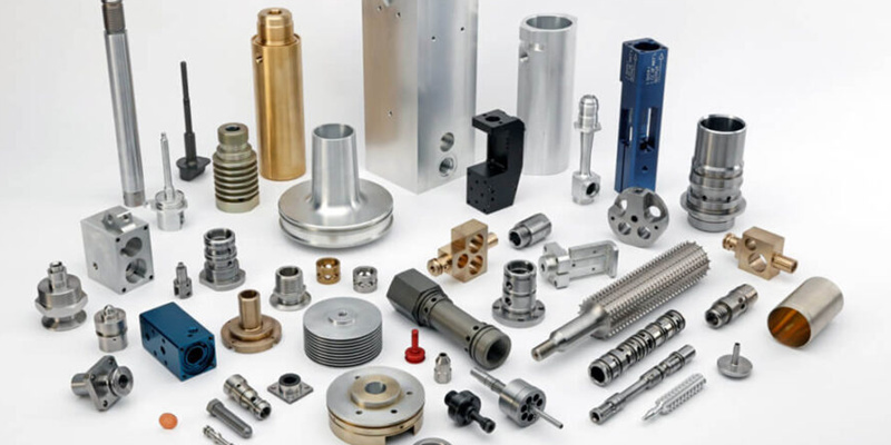
Design for Manufacturability: CNC Machined Metal Parts
Complex contours, abrupt transitions, and unreachable corners often require specialty tooling or multi-axis setups. These choices increase programming time and make inspection more complicated. By thinking about cutter paths during the design stage, it becomes easier to identify where simplification will reduce cost and improve reliability.
Use Standard Features
Standard dimensions align with common tooling and reduce cutting passes. When holes, chamfers, and radii match catalog tool sizes, the machinist can complete features with fewer steps and less tool wear. This avoids the need for custom form tools or interpolated cuts that slow production.
Useful practices include:
- Selecting hole sizes that correspond to standard drill diameters
- Using chamfer angles that match common cutters
- Applying internal radii that fit typical end mill tip geometry
Arbitrary dimensions often lead to unnecessary stock removal and additional finishing passes. Over time, this contributes to longer lead times and higher per-part costs. Standardization keeps machining predictable and repeatable.
Avoid Deep, Narrow Features
Deep pockets and narrow slots reduce tool rigidity and increase the risk of chatter. As tools extend further from the spindle, they flex more, which affects accuracy and finish. Keeping pocket depths and slot proportions within machinable limits supports cleaner cutting and better dimensional control.
Fillets inside corners help reduce stress on the tool and improve chip evacuation. Sharp internal corners force the use of very small diameter cutters, which remove material slowly. Adding even a small radius improves finish quality and reduces vibration.
Situations that often create problems:
- Pockets deeper than three times their width
- Slots that require long-reach micro tools
- Internal corners without relief radii
Designing with tool stiffness in mind supports consistent production results.
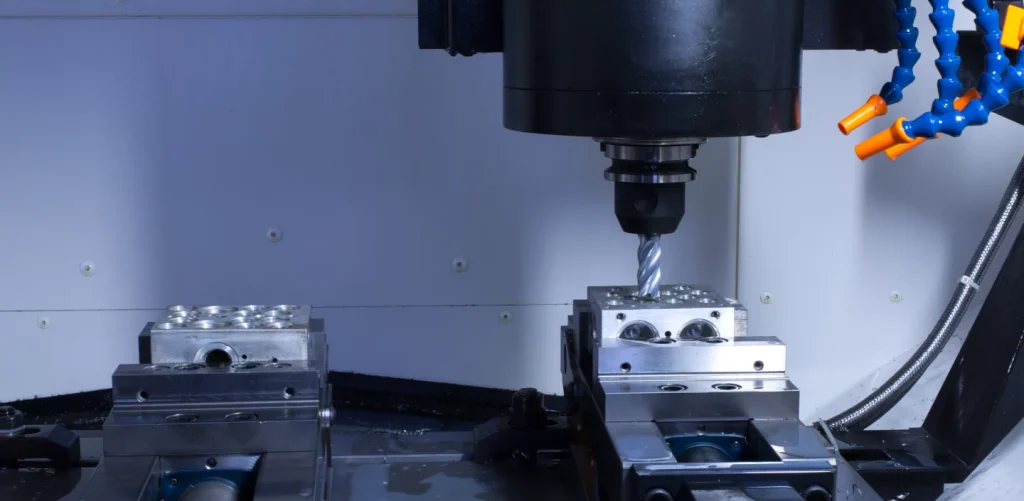
Maintain Accessible Tool Paths
Clear tool access is essential for efficient machining. When most surfaces can be reached from a limited number of orientations, parts can be completed in fewer setups. This improves accuracy because there is less repositioning and fewer opportunities for alignment variation.
If a design requires undercuts or hidden faces, higher capability equipment and specialized tooling become necessary. Five-axis machining is a valuable capability, but using it where it is not required increases cost. In many cases, splitting a complex part into simpler components results in faster machining and more predictable assembly performance.
Helpful considerations include:
- Avoiding recessed areas blocked by surrounding material
- Orienting features so they can be reached from common vice positions
- Reducing compound curves unless the function demands them
Accessible tool paths keep machining practical and reduce the risk of inconsistent finishes.
Choose Geometries That Are Easy to Machine
The geometry of a part has a direct effect on cycle time, tool choice, and surface finish. When shapes are simple and accessible, the machinist can use standard cutters, stable feeds, and predictable tool paths. This results in smoother surfaces, fewer tool marks, and lower cost. Complex shapes increase vibration, force extra repositioning, and often require specialized equipment. In practice, parts that look elegant on screen can become slow and expensive once they reach the machine. Designing with machining constraints in mind prevents these issues and keeps production efficient.
Design for Manufacturing (DFM)
Use Standard Features
Standard features allow the machinist to use common tools and predefined toolpaths. This reduces setup time and avoids custom cutters that drive up cost. Standard hole diameters, chamfer angles, and radii also shorten programming time because they align with available tool libraries.
You can improve manufacturability by:
- Matching hole sizes to standard drill diameters
- Using common chamfer angles such as 45 degrees
- Adding internal radii that correspond to standard end mill sizes
Avoiding arbitrary dimensions also prevents extra finishing passes. When dimensions do not align with tool sizes, the cutter must make additional sweeps, which increases heat, reduces tool life, and affects surface quality.
Avoid Deep, Narrow Features
Deep pockets and narrow slots create tool deflection and chatter. When tools extend too far relative to their diameter, rigidity drops, and surface finish deteriorates. This often leads to poor dimensional accuracy and longer cycle times.
A more practical approach is to:
- Limit pocket depth so tool length remains stable
- Increase slot width so standard end mills can reach without rubbing
- Add internal fillets to help the cutter move smoothly through corners
Fillets reduce stress on the cutting edge and improve chip evacuation. They also lower vibration and reduce wear, especially in harder materials. When depth cannot be reduced, consider adjusting the width or splitting the design into two simpler components.
Maintain Accessible Tool Paths
Tools need clear access to every feature. Hidden faces, sharp internal corners, and obstructed cavities force more advanced machining strategies and additional setups. This slows the job and increases the chance of an uneven finish.
To improve tool accessibility:
- Minimize features that require specialized side access
- Reduce reliance on undercuts unless the part function demands them
If the geometry begins to exceed what can be achieved on a 3-axis setup, it is often more cost-effective to redesign or break the part into separate sections that assemble cleanly. This avoids unnecessary 5-axis programming and keeps machining predictable.
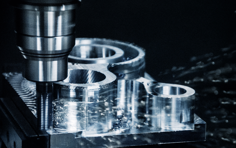
Optimize Hole and Thread Design
Holes are among the most common features in CNC-machined components, yet they become costly when designed without consideration for tool capability. Hole size, depth, and placement influence tool rigidity, chip evacuation, and feed rates. Poorly planned holes often slow machining, require specialty tooling, or lead to rough finishes and dimensional drift. Threads introduce another layer of complexity since they depend on accurate pilot holes, controlled depths, and proper relief. By aligning hole and thread design with machining realities, it becomes easier to produce consistent results while keeping the process efficient.
Follow Minimum Hole Diameters
Hole diameter should match standard drill and end mill sizes to avoid tool changes and custom cutters. Small diameter holes increase the risk of breakage and require lower feed rates, which extends machining time. They also generate heat more easily and can deform softer materials.
Practical guidelines include:
- Selecting hole sizes that correspond to catalog drill increments
- Avoiding very small holes unless the function requires them
- Replacing micro-drilled holes with larger features when possible
When a small hole cannot be avoided, it may require slower spindle speeds and reduced chip load. This increases cost, so confirming necessity during design review is worthwhile.
Manage Hole Depth
Hole depth affects chip evacuation and tool stability. Deep holes trap chips, increase friction, and require peck drilling cycles. As depth increases, tool deflection becomes more noticeable, which affects finish and dimensional accuracy.
A more efficient approach is:
- Keeping the hole depth to three times the diameter when possible
- Increasing diameter or shortening depth if repeatability is required
- Allowing through holes instead of blind holes when the design allows
Deep holes often need specialized drills or coolant-fed tools. Reducing depth or widening the hole can eliminate that requirement and shorten cycle time.
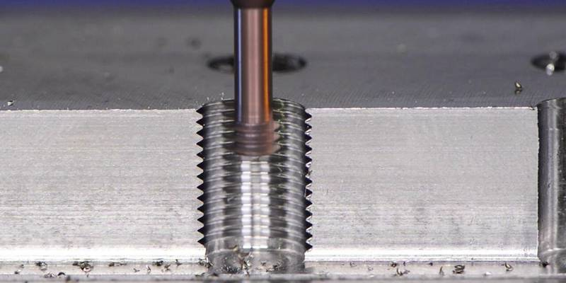
Threading Guidelines
Threads demand careful planning since tapping and thread milling require accurate access and controlled engagement. Standard thread dimensions help reduce tooling cost and simplify inspection. Excess thread depth does not improve strength because fasteners engage only within a limited length.
Recommendations for thread-friendly design include:
- Selecting standard thread sizes and common pitches
- Limiting thread depth to one to one and a half diameters
- Providing thread relief at the bottom of blind threaded holes
Thread relief reduces cutting pressure at the endpoint and prevents chipped taps or broken thread mills. For harder materials or smaller threads, relief becomes even more important because tools are more sensitive to sudden load increases.
Set Proper Wall Thickness and Rib Dimensions
Wall thickness has a strong influence on rigidity, vibration, and surface finish. When walls are too thin, the material flexes under cutting forces, and the tool begins to chatter. This produces visible marks, inaccurate dimensions, and, in some cases, distortion after the part is unclamped. Thin features also slow machining because the operator must reduce feed rates to avoid deflection. By designing walls and supporting features with machining stability in mind, it becomes easier to achieve cleaner finishes, shorter cycle times, and lower scrap rates.
Recommended Wall Thickness
Different materials respond differently during machining, so the minimum thickness depends on stiffness and hardness. Thicker walls improve rigidity, reduce vibration, and create more predictable tool engagement. They also allow larger cutters, which means faster material removal and better chip control.
Practical minimum wall thickness guidelines:
- Aluminum parts should stay within one to one and a half millimeters
- Steel and stainless parts should stay within one and a half to two millimeters
- Plastics should stay within two to three millimeters
These values support stable machining without forcing the operator to slow down. If a design requires thinner sections, reinforcing geometry or material change should be evaluated.
Strengthen With Ribs Instead of Making Walls Thicker
Increasing wall thickness adds rigidity but also adds weight and cost. Ribs provide an alternative that maintains stiffness without large material increases. Ribs also help manage deflection on broad surfaces and reduce warping after machining.
Good rib design can include:
- Using ribs instead of thickening large flat walls
- Positioning ribs to support areas likely to flex
- Adding fillets at rib intersections to distribute stress and reduce concentration
Fillets at these intersections also improve tool movement and chip flow. Sharp internal corners slow the cutter and increase wear, so filleted rib junctions support better finish quality.
Avoid Excessively Thin Floors
Pocket floors can become weak during machining if they are cut too thin. When a floor flexes under the tool, it produces uneven finishes and risks breakthrough. The larger the pocket area, the more important the floor thickness becomes because wider spans lack support.
To maintain stable floor geometry:
- Keep pocket floors above a practical minimum thickness
- Increase thickness when machining wide or deep cavities
- Review the cutter reach and diameter before finalizing the design
Adequate floor thickness also prevents heat buildup that can distort softer materials. In high-precision parts, a slightly thicker floor saves both machining time and inspection difficulty.
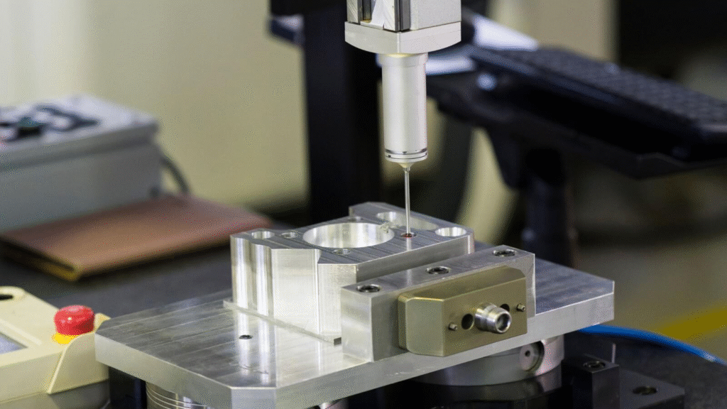
Assign Realistic Tolerances to Reduce Cost
Tolerances have one of the biggest impacts on machining cost. Tight tolerances require slower cutting parameters, more rigid setups, and additional inspection steps. When tolerances are tighter than necessary, cycle time increases and the risk of nonconformance rises. In many cases, designers apply tight tolerances across the entire part even though only a few features affect function. By assigning tolerances based on how the part interfaces and performs, the machining process becomes faster, more predictable, and less wasteful. This approach reduces both production cost and the likelihood of scrap.
Use Tight Tolerances Only Where Function Requires
Not every feature needs high precision. Tight tolerances should be limited to areas where alignment, sealing, motion, or mating components depend on accuracy. Features that do not influence assembly or performance can use looser tolerances without affecting the end use. This allows the machinist to remove material more efficiently and reduces time spent on fine finishing.
Helpful guidelines include:
- Reserving tolerances between plus or minus zero point zero one millimeters and plus or minus zero point zero five millimeters for critical features
- Keeping non-critical surfaces at plus or minus zero point one millimeters or looser
- Reviewing assemblies to confirm which features actually control fit
This selective tolerance approach improves yield and lowers inspection burden.
Consistent Datum Structure
A clear datum structure simplifies machining and measurement. When dimensions reference multiple datums or are scattered across different planes, the machinist must perform more complex setups. This increases fixture changes, repositioning, and inspection time. A consistent datum scheme also improves repeatability during production runs because the reference points remain stable.
A practical approach is:
- Using as few datums as the design allows
- Grouping tolerances around primary reference planes
- Aligning functional features to consistent coordinate origins
This keeps measurement straightforward and reduces the chance of cumulative error during assembly.
Surface Finish Requirements
Surface finish specifications affect cutter choice, step over settings, and secondary processes. A lower roughness value requires finer cutting passes, slower feed rates, and sometimes polishing. Many components do not need extremely smooth finishes to perform correctly, so specifying them increases cost without creating value.
General recommendations include:
- Requesting only the finish needed for performance or appearance
- Using roughness values between Ra one point six micrometers and three point two micrometers for most machined surfaces
- Avoiding Ra zero point eight micrometers unless sealing, sliding contact, or cosmetic expectations demand it
Setting finish requirements thoughtfully reduces machining time and extends tool life while maintaining functional quality.
Reduce Machining Time with Better Material and Setup Choices
Design for manufacturability is not only about geometry. Material choice and the way a part is held during machining also influence cost, tool wear, and surface consistency. Some materials cut cleanly and produce predictable chip formation, while others harden, deform, or generate excess heat. The setup strategy affects how many times a part must be repositioned, and every reposition increases time and introduces the risk of misalignment. By considering these factors during design, it becomes easier to produce parts faster and with fewer complications.
Material Selection
Material selection can significantly change machining performance. Softer aluminum grades machine smoothly and allow higher feed rates, while harder alloys require slower parameters and more durable tools. Materials that resist deformation during cutting also help maintain dimensional accuracy and reduce finishing passes.
Practical considerations include:
- Choosing alloys that machine cleanly, such as 6061 T6, for general components
- Avoiding harder materials like 7075 unless strength requirements justify them
- Verifying that lower-cost materials still meet load, corrosion, or thermal needs
Selecting the right material shortens cycle time, reduces tool consumption, and simplifies inspection.
Minimize Part Repositioning
Each time a part is repositioned, the machinist must realign datums and confirm accuracy. This adds non-cutting time and increases the chance of variation. Designs that allow most features to be reached in one or two setups are more efficient and more consistent.
To support fewer setups:
- Design parts so that major surfaces are accessible in a single orientation
- Add flat locating surfaces that allow reliable clamping
- Modify geometry to avoid features that hide behind other surfaces
Reducing setups improves repeatability and lowers the chance of tolerance stack issues.
Prepare for Tool Clearance and Workholding
Tool clearance determines whether the cutter can reach a feature without rubbing or interference. Workholding determines whether the part can be clamped securely without damaging surfaces. When clearance and clamping needs are not considered, the machinist must use custom fixtures, extended reach tools, or slower parameters.
To make workholding practical:
- Provide flat clamping areas that can sit securely in a vise
- Avoid features placed directly where jaws or clamps must grip
- Ensure enough vertical and lateral space for tool entry in deep cavities
These considerations prevent vibration, protect surface finish, and eliminate unnecessary fixturing complexity.
Conclusion
Thoughtful design makes CNC machining faster, cleaner, and more predictable. When geometries are simple, walls are stable, holes are practical, and tolerances match real functional needs, the machining process becomes smoother and more economical. This reduces tool wear, shortens cycle time, and lowers the chance of scrap.
Design for manufacturability is about making parts that are easy to hold, easy to reach, and easy to finish. By selecting suitable materials, reducing setups, and planning for tool access, it becomes possible to achieve better quality at a lower cost while keeping production reliable and consistent.