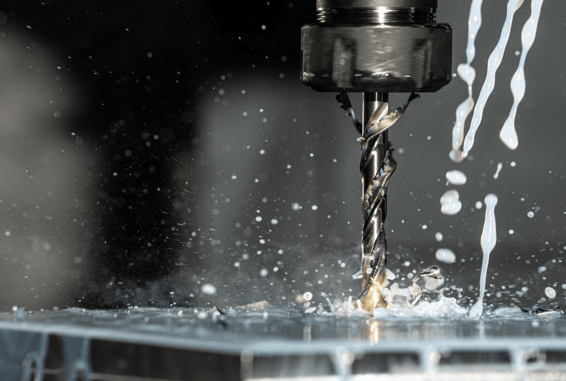
CNC machining may follow the same programming principles across materials, but the actual cutting behavior changes dramatically from one material group to another. Soft plastics react to heat and force in a completely different way than aluminum, while steels demand stronger tools and higher rigidity. At the extreme end, superalloys introduce problems like rapid work hardening, severe heat concentration, and tool wear that can escalate within minutes. These differences shape how chips form, how cutting forces are distributed, and how stable a part remains under load.

In this article, we look at how machining behavior shifts across plastics, soft metals, steels, and superalloys, and why each category needs its own approach. The sections break down material-specific cutting behavior, the tooling choices that work best for each group, the right workholding strategies, and the inspection methods required to maintain accuracy.
Machining Behavior Across Material Types
Different materials respond to cutting forces, heat, and tool pressure in very specific ways. Understanding these reactions is the foundation of material-specific machining. Plastics often deform before they cut, aluminum removes easily but creates chip evacuation problems, steels introduce higher cutting forces, and superalloys amplify heat to levels that can damage tools almost immediately. These variations affect tool selection, surface finish, and dimensional control, so each material class requires a different approach.
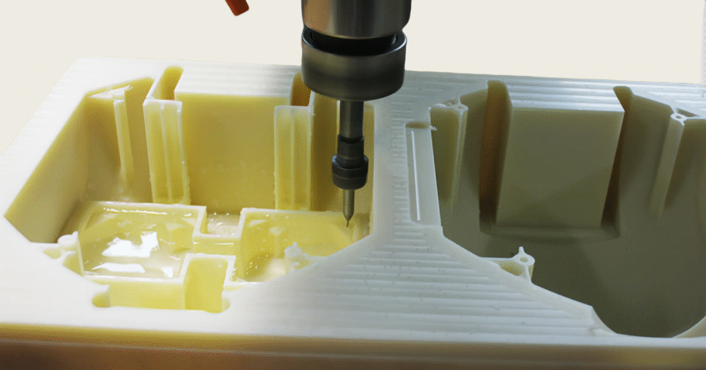
Soft Plastics (ABS, Nylon, UHMW, Acrylic)
Soft plastics behave differently because they lack stiffness and carry heat poorly. Instead of producing clean chips, they tend to melt or smear when temperatures rise, which directly affects accuracy and surface quality.
Key behavior patterns include:
- Heat sensitivity and melting
Plastics often soften long before they reach high temperatures. This softening can cause edges to smear or holes to close slightly after drilling. Light passes, and sharp tools help keep temperatures controlled.
- Burr formation and stringy chips
Many plastics create continuous, stringy chips that wrap around tools. These chips can rub against the part, cause heat buildup, or block coolant flow.
- Dimensional instability due to low stiffness
Thin features made from plastics can flex during cutting. Even small tool pressures can distort the geometry, which affects tolerance control.
- Vibration and chatter from low cutting resistance
Because plastics do not resist the tool strongly, the setup can vibrate more than expected. This results in chatter marks or uneven surfaces.
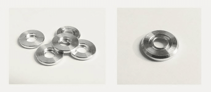
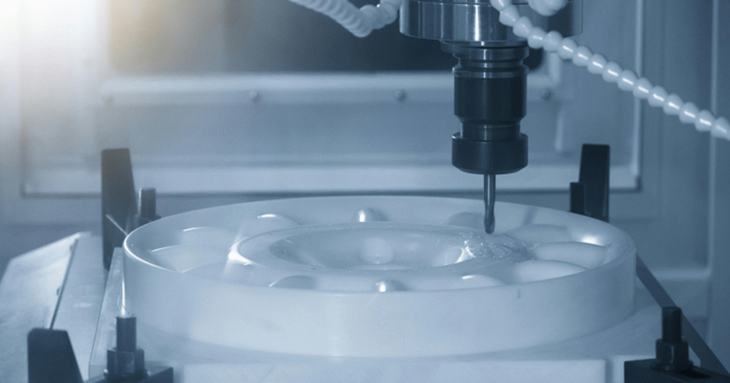
Aluminum and Other Soft Metals
Aluminum cuts easily, but the same softness that improves machinability introduces its own problems. The material is prone to sticking, which affects surface finish and tool life. Thin features can bend under load, especially in high-speed machining.
Important behavior points:
- High machinability but prone to built-up edge
Aluminum can weld itself to the tool edge if it chips or overheats. This results in poor finish and unpredictable tool wear.
- Chip evacuation challenges near pockets and thin walls
Chips tend to pack tightly in deep pockets, which raises temperatures and increases the risk of deformation.
- Risk of distortion during aggressive cuts
Thin walls or lightweight parts may flex when forces are too high, causing tolerance drift.
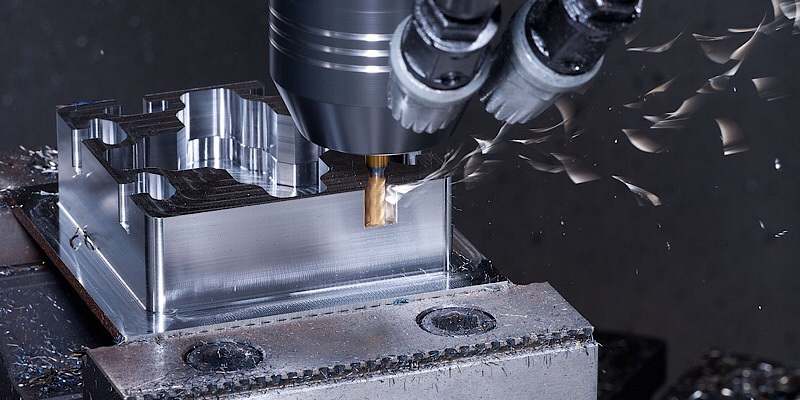
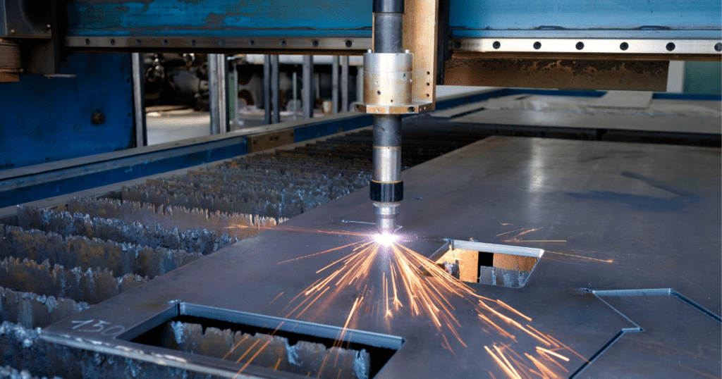
Steel and Stainless Steel
Steels introduce higher cutting forces and more sustained friction. This increases heat at the contact zone and can cause thermal distortion or tool damage if parameters are not controlled.
Behavior characteristics include:
- Higher cutting forces
The material requires stronger tools and rigid setups to withstand the load.
- Work hardening in austenitic stainless steels
If feeds are too light, the surface hardens before the next pass, making the cut significantly harder.
- Heat concentration at the tool and workpiece interface
Poor cooling can lead to dimensional changes or surface integrity issues.
Titanium, Nickel Alloys, and Hard Superalloys
These materials represent the most challenging end of the spectrum. They resist cutting, conduct heat very poorly, and punish tools if parameters are not precise. Tool wear happens faster, and the quality window becomes much narrower.
Key behaviors:
- Extremely low thermal conductivity
Most of the heat stays in the cutting zone, which damages tool edges and threatens part accuracy.
- Notch wear and rapid tool degradation
Hard superalloy chip tools quickly, especially during interrupted cuts.
- Long continuous chips
Without the correct geometry, chips form long spirals that increase tool pressure.
- Risk of microcracks from heat stress
Excessive temperatures can cause small cracks that may grow under service loads.
Tooling Strategies for Different Material Groups
Tooling choices determine how efficiently a material can be cut and how long the cutting edge survives. The tool must match the hardness, thermal behavior, and chip characteristics of the material. Plastics require sharp edges and low heat, aluminum performs best with polished geometries, steels demand strength and stability, and superalloys need the highest level of wear resistance. Once tooling aligns with the material, problems such as burrs, built-up edge, and rapid wear become far easier to control.
Tool Material Selection (Carbide, HSS, Cermet, Ceramic, PCD)
The choice of tool material has a strong effect on tool life and surface quality. Different materials behave differently under stress, heat, and vibration. Plastics and soft metals cut cleanly with sharp tools, while steels and superalloys require materials that can resist abrasion and extreme temperatures.
Key selection points include:
- Plastics
High-speed steel and uncoated carbide work well because they offer sharp edges and smooth cuts without excessive heat.
- Aluminum and soft metals
Polished carbide or PCD tools reduce sticking and maintain a clean edge for longer periods.
- Steels and hardened materials
Uncoated or coated carbide tools with high strength are preferred. Cermet can help when high wear resistance is needed during finishing.
- Superalloys
High-strength carbide and ceramic inserts handle the heat and abrasion better. Ultrafine-grain carbide helps delay tool breakdown during long cuts.
Tool Geometry and Edge Preparation
Tool geometry has a direct influence on chip flow, cutting force, and heat generation. Sharp edges reduce cutting pressure and improve finishes on soft materials, while stronger edges are needed when cutting steels and superalloys. Geometry also affects how smoothly chips evacuate from the cutting zone.
Key geometry considerations:
- Sharp edges for plastics and aluminum
A sharp edge slices cleanly and prevents melting or rubbing. Plastics benefit from a razor-like cutting edge, while aluminum needs a polished flute to avoid chip adhesion.
- Strong edges with a honed radius for steels
A slightly rounded edge withstands high loads and prevents chipping. The hone helps stabilize the cut in harder materials.
- High-rake geometries for titanium
Titanium machines better when the cutting edge lifts the chip smoothly. A generous rake angle lowers cutting force and reduces stress on the tool.
- Chip breaker designs for long-chipping materials
Breakers help curl and break the chip. This is essential for superalloys and stainless steels that naturally form long, continuous chips.
Coating Choices
Coatings change how tools handle friction, heat, and chemical wear. Some materials respond well to coated tools, while others perform better with uncoated surfaces. The goal is to keep the tool cool, prevent sticking, and improve edge durability.
Important coating guidelines:
- Avoid coatings on plastics
Coatings increase friction and heat. A clean, uncoated carbide tool produces a better finish.
- Use TiB2 and DLC for aluminum
These coatings reduce sticking and eliminate built-up edge. The smooth surface helps chips leave the flute more easily.
- Apply TiAlN and AlTiN for steels
These coatings provide heat resistance during high-load cuts. They also help protect the tool during interrupted operations.
- Use advanced multilayer coatings for superalloys
Multilayer coatings offer thermal stability and withstand abrasive wear. This helps delay tool failure during long, demanding cuts.
Toolpath and Feed Strategies
Toolpath strategy influences cutting pressure, temperature rise, and chip evacuation. Soft materials benefit from high speeds and light engagement, while hard materials need controlled tool engagement to avoid excessive heat.
Effective toolpath principles:
- High-speed machining for plastics and aluminum
Fast spindle speeds and light cuts keep heat low and reduce tool marks. Finishes improve when the tool moves quickly across the surface.
- Constant tool engagement for steels
Steels respond well when the tool stays under a steady load. Toolpath smoothing and adaptive milling help prevent spikes in pressure.
- Low radial engagement with higher feed rates for superalloys
Removing small radial amounts reduces heat buildup. The higher feed helps the tool stay ahead of work hardening.
Workholding Requirements Across Materials
Workholding has a direct influence on accuracy, surface finish, and tool performance. Each material reacts differently to clamping pressure, heat, and vibration, so the fixture strategy must adjust to the behavior of the workpiece. Plastics deform under pressure, aluminum can bend during aggressive roughing, steels demand a rigid setup, and superalloys require maximum stability because the cutting forces are high. When workholding aligns with material properties, it becomes easier to maintain tolerances and reduce scrap.
Plastics
Plastics are the most sensitive to clamping pressure because of their low stiffness. Even small amounts of force can distort the shape, especially when cutting thin sections or flexible components. Heat from machining can also cause temporary expansion, which complicates dimensional accuracy.
Key workholding considerations for plastics:
- Low clamping pressure to avoid deformation
Light clamping is often enough for stable machining. Soft jaws or smooth vise pads help distribute pressure evenly.
- Support for thin-wall features
Machined supports, backup plates, or temporary fill materials help prevent flexing during contouring or pocketing.
- Vacuum fixturing for sheet and plate plastics
Vacuum fixtures work well for large flat parts by providing uniform holding without crushing the material.
Aluminum and Soft Metals
Aluminum is more stable than plastic but still prone to distortion when clamped too tightly or machined aggressively. Thin walls, pockets, and lightweight structures require careful support to ensure accuracy.
Common workholding needs include:
- Standard vises and modular fixturing
Aluminum typically holds well in conventional fixtures, especially with properly machined soft jaws.
- Avoiding distortion in thin parts
Thin sections can flex under cutter load. Parallel supports, tabs, or temporary ribs help maintain rigidity.
Steels and Stainless Steels
Steels introduce higher cutting forces, which increase the load on the fixture. A rigid setup is essential to avoid vibration and maintain dimensional control. Stainless steel can also expand due to heat, so workholding must support extended machining without movement.
Important points for steel workholding:
- High clamping forces
Steels require strong and stable clamping to resist the forces generated during roughing passes.
- Rigid fixturing to resist cutting load
Fixtures should minimize movement. Four-jaw vises, heavy bases, or precision clamps help keep the part stable.
- Support for deep cavities
Parts with tall walls or deep pockets benefit from additional supports or internal bracing to prevent movement during machining.
Titanium and Superalloys
Titanium and superalloys require the most robust workholding because of their high cutting resistance. The tool exerts more pressure on the part, and the heat produced can cause thermal growth. These materials also tend to be expensive and often have tight tolerances, so the fixture must prevent any unwanted movement.
Key workholding considerations include:
- Maximum rigidity to counter strong cutting forces
Solid fixtures, custom plates, and multi-contact setups help stabilize the part during heavy operations.
- Thermal expansion considerations
Long machining cycles can heat the part. Fixtures must allow for controlled expansion without losing accuracy.
- Multi-axis workholding to reduce setups
Reducing repositioning improves accuracy and avoids cumulative errors. Multi-axis clamps and trunnion tables are often used for these materials.
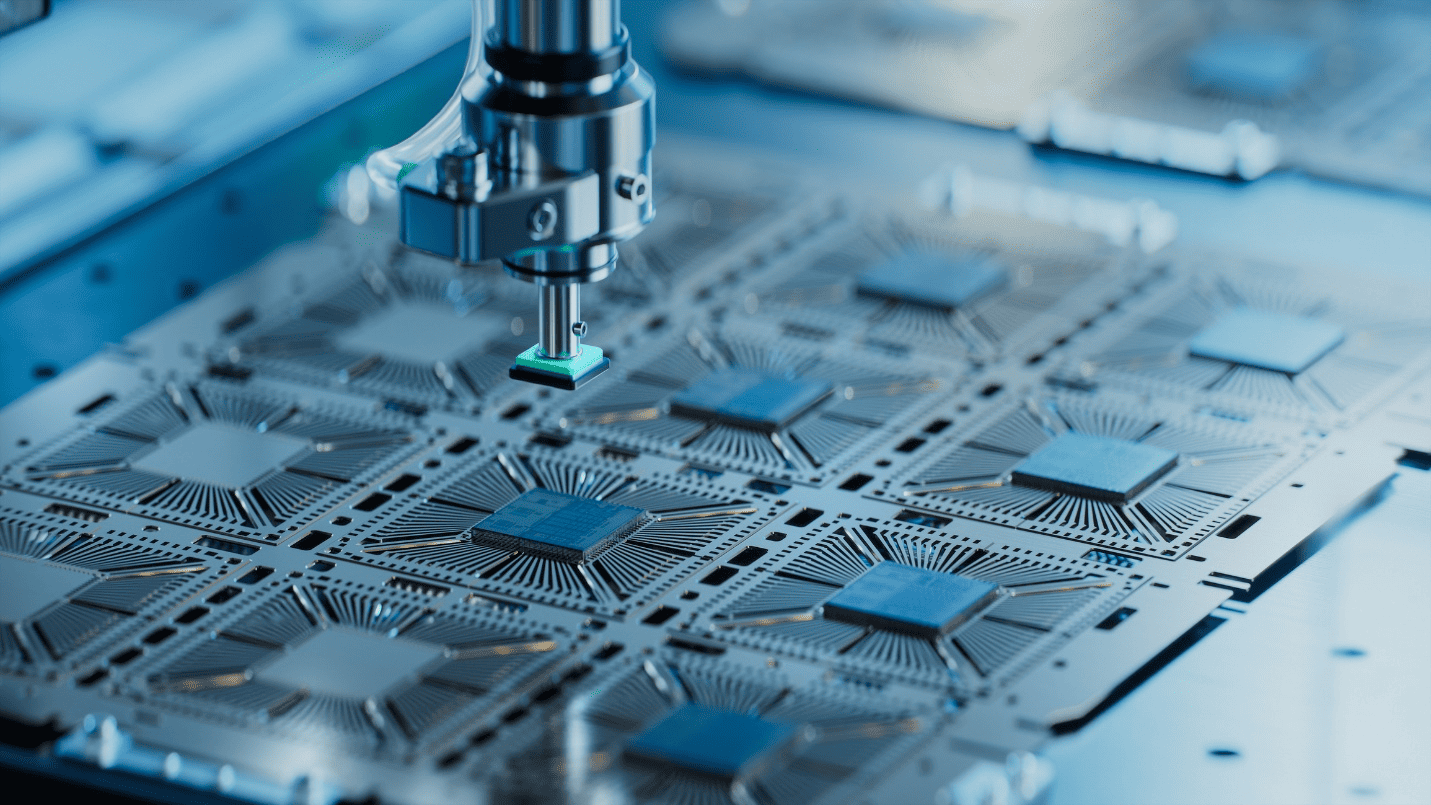
Inspection and Quality Control by Material Type
Inspection requirements shift significantly depending on the material being machined. Plastics may warp after cutting, aluminum often shows micro burrs, steels can distort from heat, and superalloys demand extremely precise checks because they are used in high-reliability sectors. Each material brings a different type of risk, so measurement and verification must be adapted to the behavior of the part after machining. When inspection follows material-specific patterns, dimensional accuracy becomes more consistent and scrap rates drop.
Plastics
Plastics require careful inspection because they expand with heat and may slowly relax after machining. This makes it difficult to measure the part immediately after the tool lifts away. The material can continue to shrink or shift slightly, especially if the machining process generated local heat.
Key inspection points for plastics:
- Dimensional inspection after thermal stabilization
Measurements should be taken once the part returns to room temperature. This reduces errors caused by temporary expansion.
- Checking for warping or creep
Flat surfaces and long profiles should be checked for subtle deflection. Plastics may bend over time, even with low cutting forces.
- Surface finish inspection for melting or tool marks
A close visual check confirms whether the tool created smearing or melted edges. This is common in acrylic or nylon when the feeds are too light.
Aluminum and Soft Metals
Aluminum parts are relatively stable but still require checks for features that can be affected by high-speed machining. Thin walls, fine details, and deep pockets may distort slightly. Burrs also appear easily along edges, so inspection must include both dimensional and cosmetic evaluation.
Important inspection tasks include:
- Concentricity and flatness checks
Features such as bores, counterbores, and sealing faces should be measured to confirm they stayed true during machining.
- Detecting chatter or micro burrs
High-speed passes can leave small chatter marks. Burrs often appear on internal edges, so they must be removed and verified before assembly.
- Surface finish measurement
Roughness gauges or optical checks help confirm whether the finish meets functional requirements.
Steels and Stainless Steels
Steels tend to hold shape well, but heat from roughing or long tool engagement can lead to subtle dimensional changes. Stainless steels can also work harden, which affects surface integrity and part performance. Inspection, therefore, focuses on confirming both size and material condition.
Key points for steel inspection:
- Hardness verification after machining
Hardness tests confirm that excessive heat did not alter the material properties, especially in critical components.
- Dimensional control for heat-induced distortion
Parts with long cuts or heavy roughing should be checked for slight bowing or taper. Even small distortions can affect fit.
- Surface integrity checks
The surface must be inspected for burn marks, tearing, or debris left from work hardening.
Titanium and Superalloys
Titanium and superalloys require the most rigorous inspection because they are often used in aerospace, medical, and high-stress applications. These materials can develop microcracks or heat-related defects that are not visible to the eye. Precision measurement is necessary to ensure that all features meet tight tolerances.
Critical inspection guidelines include:
- Non-destructive testing for microcracks
Dye penetrant, ultrasonic testing, or eddy current inspection helps identify cracks that form under heat or high tool pressure.
- High-accuracy CMM inspection for tight tolerances
Coordinate measuring machines provide the accuracy required for complex geometries and small tolerances.
- Surface integrity and tool wear signature analysis
The surface should be checked for patterns that indicate tool breakdown. This helps confirm both part quality and tool performance during machining.
Practical Tips for Material-Specific CNC Optimization
Optimizing CNC machining across different materials requires adjusting more than just spindle speed or feed rate. Each material group responds to heat, pressure, vibration, and tool geometry in a unique way. A strategy that works well for aluminum may fail on nylon, and a tool that performs reliably in steel may wear out rapidly in titanium. When machinists tailor their approach to the material, productivity increases and parts come off the machine with fewer defects.
Match tool geometry to chip type
Chip behavior controls tool pressure, surface quality, and heat buildup. Materials that form long, continuous chips require geometry that encourages breaking or curling. Materials that melt or smear need sharp, high-rake tools to create clean shearing.
Practical guidance:
- Use polished, sharp tools for plastics and aluminum to avoid rubbing.
- Select chip breakers for steels and superalloys to prevent chip wrapping.
- Choose rake angles that reduce cutting force in tougher materials.
Control heat for plastics and superalloys
Heat acts differently in plastics and superalloys. Plastics soften quickly, which affects dimensional stability. Superalloys trap heat near the cutting zone, which accelerates tool wear. Both material types demand temperature management, but in different ways.
Useful adjustments:
- Increase surface speed and reduce depth of cut when working with plastics.
- Improve coolant delivery for superalloys to prevent thermal spikes.
- Reduce radial engagement to limit heat concentration in difficult materials.
Choose workholding based on stiffness
Workholding must match the rigidity of the material and the geometry of the part. Soft materials deform easily when clamped, while hard materials require maximum stability to resist tool pressure.
Recommendations:
- Use low clamping pressure for plastics to avoid distortion.
- Support thin aluminum parts with soft jaws or parallel backing.
- Secure steel and superalloy parts with rigid fixtures to counter high cutting loads.
Inspect parts with material behavior in mind
Inspection needs change depending on how the material reacts during and after machining. Some parts require time to stabilize, while others need special checks for surface integrity or microcracks.
Inspection considerations:
- Allow plastics to cool fully before measuring.
- Check aluminum parts for chatter or burrs along edges.
- Use high-accuracy equipment for superalloys where tolerances are tight.
- Apply non-destructive testing for critical titanium components.
Conclusion
Material behavior influences every stage of CNC machining, from tool selection to inspection. Plastics, aluminum, steels, and superalloys each react differently to heat, pressure, and chip formation, which means a single approach can never deliver consistent results across all materials. When machinists understand these differences, they can plan toolpaths, choose tools, and set workholding conditions that support accuracy rather than fight against the natural tendencies of the material.
A material-specific strategy reduces scrap, improves surface finish, and extends tool life. It also helps maintain predictable quality when shifting between simple plastics and high-performance superalloys. With the right combination of tooling, fixturing, and inspection methods, each material can be machined efficiently and reliably, even when tolerances are tight or the application is critical.