Precision is the foundation of CNC machining. Every part, from aerospace turbine components to optical mounts, depends on dimensional accuracy that can reach the micron level. At this scale, even small temperature changes can shift dimensions enough to cause a part to fail inspection. This is why advanced machining is not only about toolpaths and machines but also about managing the invisible factor that alters size, shape, and alignment: heat.
Thermal Expansion in CNC Machining
Tight-tolerance machining involves working within limits so narrow that the natural expansion and contraction of materials can’t be ignored. When a machine warms up, the spindle and ballscrews grow slightly in length. When a tool cuts for too long, it heats and expands. When a workpiece absorbs heat from the tool or coolant, its dimensions change; each of these variations, measured in microns, affects accuracy. Understanding and controlling these thermal effects separates consistent, repeatable precision from random variation.
This article is to explore how temperature influences accuracy in CNC machining and to present effective ways to counter it. You will learn how thermal expansion occurs, how to stabilize machines and environments before cutting, and how to apply practical compensation strategies.
Understanding Thermal Expansion in CNC Machining
Precision machining depends on dimensional stability. Yet, every material used in CNC manufacturing, from the cast iron of a machine bed to the aluminum of a workpiece, responds to heat. When temperatures fluctuate, materials expand or contract. Even a small rise of a few degrees Celsius can alter part dimensions by several microns. Understanding this phenomenon is essential before trying to control it.
What is Thermal Expansion?
Thermal expansion is the increase in a material’s dimensions as its temperature rises. On a microscopic level, heat energy causes atoms to vibrate more vigorously, increasing the average distance between them. This change in atomic spacing is expressed through the Coefficient of Thermal Expansion (CTE), usually measured in micrometers per meter per degree Celsius (µm/m°C).
For example:
- Aluminum has a CTE of around 23 µm/m°C, which means a 100 mm part will grow by 2.3 µm for every 1°C increase.
- Steel’s CTE is about 11–13 µm/m°C, expanding roughly half as much.
- Invar, used in high-precision instruments, has a very low CTE of 1.2 µm/m°C, making it dimensionally stable under temperature changes.
These values show why some materials demand tighter thermal control. A machine shop maintaining ±5 µm tolerance cannot afford a few degrees of uncontrolled heat drift.
How Thermal Expansion Affects Machining Accuracy
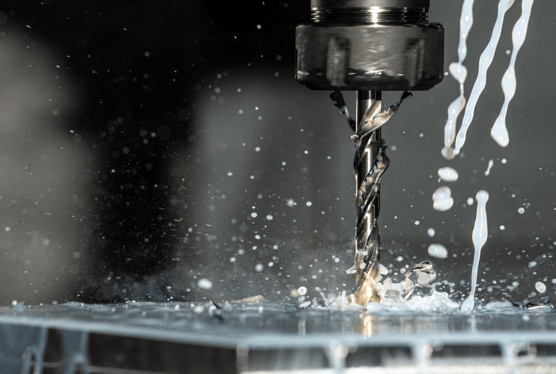
During CNC machining, heat is generated in multiple zones. The cutting tool, workpiece, and machine structure all absorb energy differently. If this heat is not stabilized, the system deforms in unpredictable ways.
Thermal Compensation in CNC Machines
Key effects include:
- Tool growth: When the cutting tool expands, it slightly increases its effective cutting length, changing the size or depth of features.
- Workpiece distortion: Heat absorbed by the material causes expansion that alters part geometry, especially in long or thin components.
- Machine drift: Spindles, guideways, and ballscrews expand along their axes, affecting positional accuracy.
Even a 10°C rise in a steel machine structure can elongate a 1-meter ballscrew by more than 100 µm, enough to destroy tolerances in micron-level operations.
Where Micron-Level Deviations Matter
Some industries are highly sensitive to thermal variation because their parts must perform with extreme precision.
- Aerospace components: Tolerance stacking in assemblies like turbine blades or actuators can lead to performance loss or vibration if parts vary by even 10–15 µm.
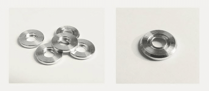
- Optical parts: Lens housings or mounts must hold alignment within microns to ensure optical paths remain true.
- Medical devices: Surgical tools, implants, and diagnostic equipment require precise fits to maintain safety and function.
In all these cases, thermal expansion errors cannot be “polished out” or corrected after machining. They must be prevented through control and compensation.
Why Temperature Variations Are Unavoidable
No machining environment remains at a constant temperature. Machines heat up during spindle rotation. Coolant systems transfer heat unevenly. The surrounding air changes throughout the day. Even measuring instruments experience slight drift.
Factors contributing to thermal variation include:
- Machine warm-up cycles and duty load.
- Ambient temperature swings in the workshop.
- Coolant temperature rises with prolonged use.
- Cutting speed and material hardness increase frictional heat.
Recognizing that these fluctuations are inevitable allows machinists to focus not on elimination but on management and prediction, the core of thermal expansion control.
Thermal expansion is a predictable, measurable behavior. When understood, it becomes possible to plan around it rather than react to it. The next step is to control how and when temperature changes occur inside the machine and the workshop environment. That begins with proper machine warming and environmental stabilization.
Machine Warming Cycles and Environmental Stability
Temperature control begins long before the first toolpath runs. A CNC machine that has been idle overnight behaves differently from one that has been running continuously for hours. Metals inside the spindle, ballscrews, and guideways expand as they heat up, shifting alignment and altering the geometry of motion. To achieve micron-level consistency, the machine must reach a stable thermal state before production begins.
Importance of Pre-Heating Machines
Warming cycles allow the entire mechanical structure to expand to its normal operating condition before critical machining starts. When machines are powered on cold, each moving component heats at a different rate. This uneven expansion introduces positioning errors that appear as size variations in the first few parts.
The goal of pre-heating is not simply to raise the temperature but to equalize it across the system. Once all critical elements, spindle, ballscrews, and guideways, reach a consistent operating temperature, dimensional drift during cutting becomes minimal. In high-precision environments, this stabilization can mean the difference between a first-time-right component and hours of re-work.
Recommended Warming Cycles for Spindles, Ballscrews, and Guideways
Each machine component responds to heat differently, so warming routines should target them individually.
- Spindle warming: Gradually increase spindle speed in steps (for example, 500 rpm increments every 3–5 minutes) until reaching normal operating speed. This ensures bearings and lubrication systems reach equilibrium without generating hotspots.
- Ballscrew activation: Jog each axis repeatedly through its full travel at moderate feed rates. This movement distributes lubricant, raises temperature evenly, and prevents localized expansion at the ends.
- Guideway motion: Use low-feed traverses across axes to warm linear guideways uniformly. For hydrostatic or air-bearing systems, stable temperature ensures fluid film consistency and minimal friction variation.
After 20–30 minutes of controlled cycling, the machine will stabilize thermally, reducing size variation between the first and last parts of a batch.
Stabilizing the Shop Environment
Even the best warm-up routine cannot compensate for a changing ambient environment. Temperature fluctuations in the workshop air directly affect both the machine and the workpiece. Ideally, a precision machining room should maintain ±1°C temperature stability and consistent humidity.
Key environmental practices include:
- Temperature control: Use air conditioning or heating systems to maintain a constant room temperature. Avoid placing machines near doors or windows where drafts can create uneven air pockets.
- Humidity management: Maintain humidity around 50% to prevent corrosion and ensure stable air density for coolant atomization.
- Airflow consistency: Ensure fans and vents do not blow directly on machines or parts. Constant airflow direction and speed reduce local temperature differences.
For ultra-precision work, some shops install insulated enclosures or climate-controlled cubicles around critical machines. This isolates them from daily environmental swings that can reach several degrees.
Case Examples from Precision Workshops
Aerospace and optical component facilities provide good models of environmental discipline.
- Aerospace machine cells often operate in climate-controlled zones where temperature is logged continuously. Machines are kept running at idle during breaks to maintain thermal consistency.
- Optical manufacturing labs use granite tables and temperature-regulated coolant systems. Their rooms are typically held within ±0.5°C to prevent any distortion in lens mounts or mirror substrates.
In both cases, the investment in temperature stability yields measurable benefits: consistent tolerances, predictable process control, and longer machine calibration intervals.
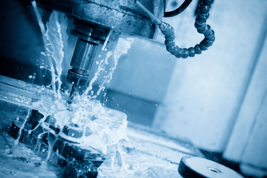
Coolant Management and Thermal Control
Coolant is more than a chip-clearing fluid. In high-precision CNC machining, it acts as a temperature regulator that controls the heat generated by cutting, friction, and tool contact. When coolant temperature fluctuates, it transfers uneven heat to both the tool and the workpiece, leading to distortion. Therefore, coolant management is one of the most direct and effective methods for controlling thermal expansion during machining.
Coolant Management and Thermal Control
The Role of Coolant in Temperature Stabilization
During cutting, friction between the tool and workpiece converts mechanical energy into heat. If not removed effectively, this heat accumulates in the cutting zone and gradually spreads through the tool, spindle, and workpiece. Coolant dissipates this energy, keeping temperatures near equilibrium.
However, coolant can only perform this function if its temperature remains consistent. When coolant itself heats up from recirculation or prolonged use, it ceases to cool effectively. Instead, it introduces thermal drift that alters part size and surface finish. The ideal coolant system absorbs heat rapidly, removes it from the cutting zone, and returns to a stable temperature before re-entering the process.
Maintaining Consistent Coolant Temperature
The stability of coolant temperature is critical when machining tight-tolerance parts. Even a small variation in coolant temperature can change part dimensions within microns.
Key factors to maintain consistent coolant conditions:
- Coolant chillers: Use temperature-controlled chillers to keep coolant within ±1°C of the ambient machine temperature.
- Thermal insulation: Insulate coolant tanks and pipelines to minimize heat exchange with the surrounding air.
- Flow rate consistency: Maintain steady pressure and flow to avoid temperature spikes during tool changes or heavy cuts.
- Coolant circulation time: Allow sufficient dwell time in the tank for coolant to cool before recirculating.
Regular monitoring of coolant temperature ensures it remains an ally in precision, not a source of error.
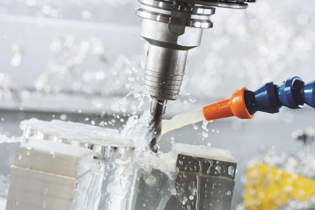
Choosing the Right Coolant System for Tight-Tolerance Applications
Different machining setups require different coolant delivery systems. Choosing the right one depends on material type, part geometry, and required surface finish.
Common coolant systems include:
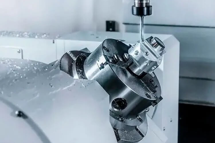
- Flood coolant systems: Effective for general machining, providing bulk heat removal. However, they can cause uneven cooling on small precision parts if not directed accurately.
- Through-tool coolant systems: Deliver coolant directly through the spindle and cutting tool, improving control of temperature at the tool tip and minimizing thermal distortion.
- High-pressure systems: Essential for deep-hole drilling or high-speed cutting, where heat accumulation and chip evacuation are major challenges.
- Oil-based vs. water-based fluids: Water-based coolants offer better heat conductivity, while oil-based coolants provide lubrication and reduce tool wear. Selection should balance cooling and lubrication requirements for each material.
For ultra-precision parts, a temperature-controlled coolant loop with sensors and feedback control is preferred to maintain continuous stability.
Monitoring and Feedback Systems for Coolant Control
Modern CNC machines often integrate temperature sensors and thermal feedback systems that monitor both coolant and machine temperatures in real time. These systems can automatically adjust coolant flow or trigger alarms when temperature deviations exceed limits.
Effective monitoring practices include:
- Inline temperature sensors: Measure coolant temperature before and after it passes through the cutting zone.
- Digital feedback loops: Connect sensors to the CNC controller, enabling automatic compensation for thermal variation.
- Data logging: Record coolant temperature trends throughout production to identify gradual thermal shifts or system inefficiencies.
By integrating these systems, machinists can identify and correct temperature-related errors before they affect dimensional accuracy.
Case Insight: Precision Aerospace Component Cooling
In aerospace machining, parts such as actuator housings and valve seats often require tolerances within ±3 µm. One manufacturer implemented a temperature-regulated coolant system operating at a fixed 22°C, synchronized with the ambient room temperature. This alignment minimized heat gradients between the coolant, machine, and workpiece, resulting in a consistent size variation below 1 µm across multiple batches.
This example illustrates how controlled coolant systems not only preserve tolerances but also improve repeatability and reduce scrap rates.
Compensation Strategies for Thermal Expansion
Even with stable temperatures and careful coolant control, some degree of thermal expansion is unavoidable in CNC machining. The challenge is not to eliminate it completely but to predict, measure, and compensate for it effectively. Advanced compensation methods allow machinists and engineers to maintain accuracy within a few microns even under changing thermal conditions.

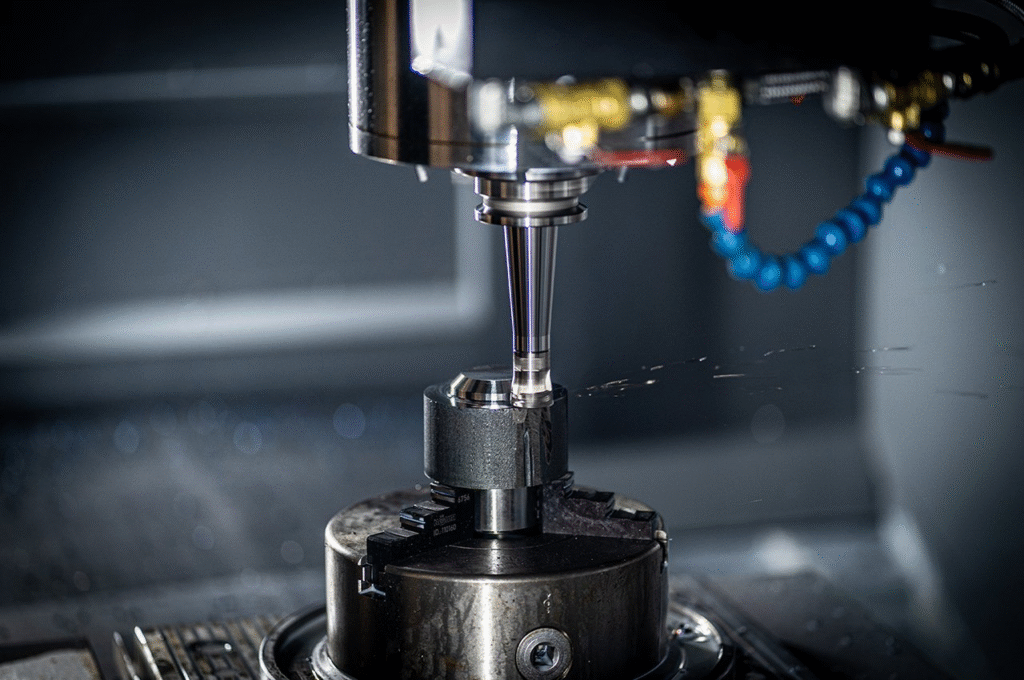
Thermal Compensation in CNC Machines
The Role of Software-Based Compensation
Modern CNC controllers include software systems designed to detect and offset thermal distortion automatically. These systems rely on mathematical models and sensor data to predict how heat affects machine geometry and part size.
When the machine warms up, its structural components, such as the spindle and ballscrews, elongate slightly. Without correction, this elongation shifts the toolpath and changes the actual cutting position. Thermal compensation software measures the temperature at key points, applies the corresponding correction factors, and adjusts the tool position dynamically.
Common compensation features include:
- Spindle growth compensation: Uses embedded sensors near the spindle bearings to calculate thermal expansion along the Z-axis and adjust tool length automatically.
- Ballscrew elongation compensation: Corrects axis positioning errors caused by expansion in long-travel ballscrews.
- Table temperature compensation: Adjusts coordinate values based on the temperature of the machine table to ensure the workpiece remains centered correctly.
These adjustments are often updated in real time, maintaining consistent accuracy throughout long production cycles.
Building Reliable Thermal Models
A reliable thermal compensation model depends on understanding how each part of the machine reacts to heat. Machine tool builders often run extensive calibration tests, recording the displacement caused by different temperature ranges. These data sets form the foundation of the machine’s internal compensation logic.
For custom or older machines, manual calibration can be performed by:
- Recording positional drift at specific temperature increments.
- Establishing linear correction coefficients for each axis.
- Updating these coefficients periodically as the machine wears.
Well-calibrated models help the machine predict dimensional changes before they occur, allowing preventive correction rather than reactive adjustment.
Material-Specific Strategies
Thermal expansion also depends on the material being machined. Each metal responds differently to temperature, and overlooking this behavior leads to uneven tolerances, especially in assemblies involving multiple materials.
Understanding the Coefficient of Thermal Expansion (CTE):
The CTE defines how much a material expands per degree of temperature increase. Materials with high CTEs are more sensitive to heat and need greater compensation or tighter thermal control.
Measuring the CTE (coefficient of thermal expansion)
Approximate CTE values for common materials:
- Aluminum alloys: 22–24 µm/m°C
- Stainless steel: 16–17 µm/m°C
- Titanium alloys: 8–9 µm/m°C
- Invar (nickel–iron alloy): 1–2 µm/m°C
Practical strategies for each category:
- Aluminum: Machine under controlled coolant temperatures and avoid long continuous passes that generate heat. Use fast cutting speeds with high coolant flow.
- Stainless steel: Use lower feed rates to reduce heat buildup and allow time for thermal dissipation.
- Titanium: Balance cutting speed and tool wear carefully, as titanium retains heat.
- Invar: Minimal thermal expansion, but maintains environmental stability to prevent uneven cooling or condensation.
Matching tool material and coolant to workpiece behavior ensures that both expand predictably and remain within the tolerance range.
Process Planning for Heat Management
Thermal stability begins in the planning phase. The order and duration of machining operations influence how heat accumulates in both the tool and the part. Poor sequencing can trap heat in one region, causing uneven expansion that distorts dimensions.
Key process-planning techniques include:
- Short-cycle machining: Break long operations into smaller segments with pauses to allow heat dissipation.
- Balanced material removal: Alternate between sides or surfaces to equalize temperature across the workpiece.
- Toolpath optimization: Avoid repetitive cutting passes in confined areas that lead to localized heat concentration.
- Adaptive feed and speed control: Modern CAM software can automatically vary cutting parameters based on temperature prediction or tool engagement levels.
Well-planned processes reduce heat gradients, enabling compensation systems to work within predictable limits.
Integrating Real-Time Temperature Feedback
Temperature feedback loops close the gap between prediction and real-world variation. Many high-end machines feature embedded thermal sensors along the spindle, table, and axes. These sensors continuously relay temperature data to the control system, allowing on-the-fly corrections.
In some setups, the workpiece or fixture may also include temperature probes. Data from these sensors is used to apply offset adjustments dynamically, ensuring that cutting dimensions remain stable even during long machining cycles.
Benefits of real-time thermal feedback:
- Continuous accuracy monitoring.
- Automatic response to rapid temperature shifts.
- Reduced operator intervention and error.
This approach turns temperature into a controlled variable rather than a random disturbance.
Case Study: Aerospace Component Requiring ±5 µm Tolerance
An aerospace supplier machining titanium actuator housings faced size drift during long production runs. By integrating real-time spindle and ballscrew temperature sensors, the CNC control compensated dynamically for each thermal shift. Coolant temperature was stabilized at 21°C, matching ambient air. The result was a reduction in dimensional deviation from 15 µm to below 3 µm per batch.
This improvement allowed the manufacturer to meet stringent aerospace tolerances consistently without manual offset adjustments or downtime.
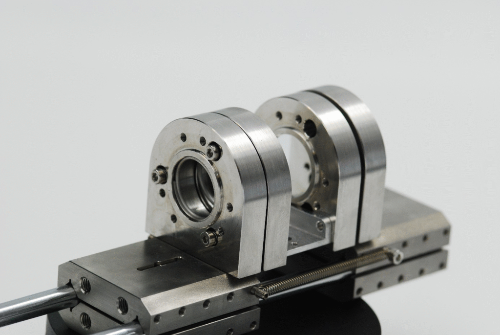
Case Study: Optical Lens Mounts and Precision Instruments
A manufacturer of optical mounts for laser systems faced alignment issues due to temperature differences between morning and afternoon shifts. Implementing a climate-controlled cell, uniform coolant temperature of 22°C, and predictive offset tables in the CNC software stabilized tolerances. As a result, lens concentricity errors dropped from 8 µm to less than 2 µm, maintaining optical alignment throughout production.
These results show that precise compensation is a system-level solution combining software, sensors, and environment, not a single adjustment or setting.
Thermal compensation in CNC machining depends on three pillars: predictive modeling, material-specific control, and real-time correction. When these are applied together, they transform temperature from a hidden threat into a manageable factor. With proper compensation, even complex, multi-hour machining cycles can maintain micron-level accuracy regardless of environmental fluctuations.
Best Practices for Maintaining Micron-Level Accuracy
Controlling thermal expansion is not limited to one technique or phase of machining. It is a continuous discipline that combines machine maintenance, process design, and operator awareness. Even with compensation systems and stable environments, precision can drift if daily practices are inconsistent. The following methods help maintain repeatable accuracy under varying shop conditions.
Overcoming Thermal Expansion Challenges
Regular Calibration of Machines and Measuring Instruments
Precision cannot be maintained without verified accuracy of both machines and measurement tools. Calibration ensures that thermal corrections and positional data remain valid over time.
Machine calibration should include:
- Axis alignment checks: Use laser interferometers or ballbar tests to detect deviations caused by thermal distortion or wear.
- Spindle runout measurement: Verify spindle concentricity at operating temperature. A warm spindle can expand unevenly, affecting circular interpolation.
- Probe calibration: Confirm the accuracy of touch probes and tool setters under stable room temperature. Small probe errors can translate to significant machining offsets.
For measuring instruments such as micrometers, CMMs, and height gauges, maintain them in the same temperature zone as the machining cell. Instruments stored in cooler or warmer rooms will read differently when brought to the part.
Short-Cycle Machining and Intermittent Cooling
Long machining cycles without pauses allow heat to accumulate progressively. The tool, workpiece, and fixtures absorb and retain this heat, creating uneven expansion. Dividing operations into shorter cycles helps control this buildup.
Practical approaches include:
- Machining complex parts in stages with cool-down intervals between roughing and finishing.
- Performing semi-finishing passes to relieve heat before final cuts.
- Using air blasts or mist cooling between cycles to stabilize surface temperatures.
These pauses allow both the tool and part to return closer to ambient conditions, minimizing dimensional drift in subsequent cuts.
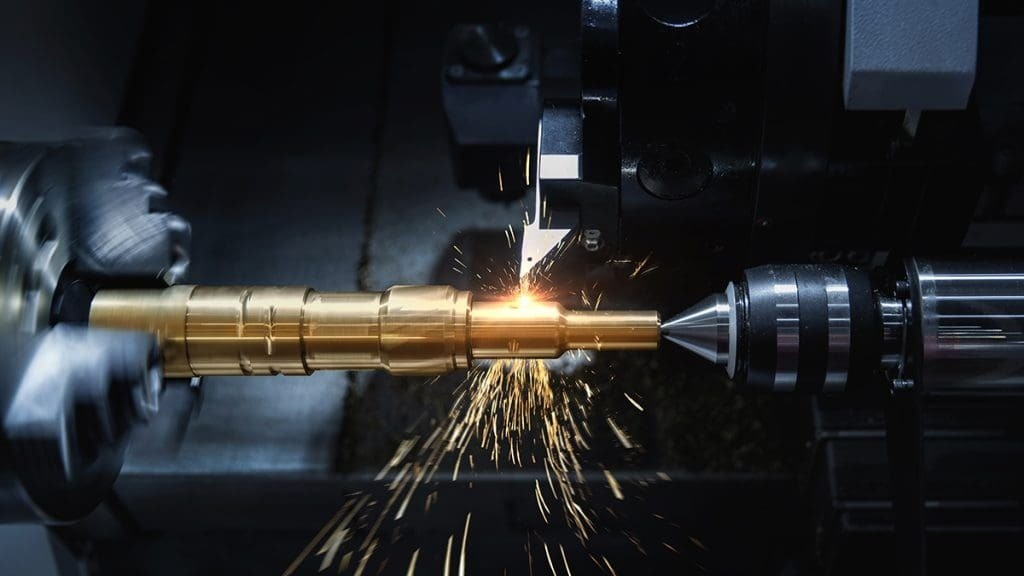
Continuous Monitoring of Tool and Spindle Temperatures
Temperature variation in the spindle and cutting tool directly influences dimensional consistency. Monitoring these areas ensures real-time visibility of thermal trends before errors appear in finished parts.
Methods for temperature tracking include:
- Infrared sensors: Non-contact monitoring of spindle housing and tool holder surfaces.
- Built-in thermocouples: Some high-end spindles integrate thermocouples that record internal temperature changes.
- Data visualization software: Displays live temperature data to operators, helping them adjust feed rates or coolant parameters if heat buildup occurs.
By keeping the cutting interface within a predictable thermal range, tool wear and surface finish remain consistent throughout the job.
Integrating Thermal Considerations into Fixture and Tooling Design
Fixtures and tools are often overlooked sources of thermal distortion. Poor design or material choice can cause uneven expansion, misalignment, or vibration. Considering thermal properties at the design stage prevents errors later in production.
Important fixture design guidelines:
- Use materials with low CTE, such as cast iron or Invar, for base plates and alignment surfaces.
- Ensure symmetrical clamping to distribute heat evenly and prevent part warping.
- Allow for thermal relief slots or expansion gaps in long fixtures.
- Design contact points to minimize localized heat transfer from the tool to the part.
For tooling:
- Use balanced tool holders that reduce vibration and heat generation.
- Ensure proper seating of tools to prevent micro-gaps that accumulate heat.
- Select tool materials suited to the workpiece’s thermal conductivity.
By engineering fixtures and tooling for thermal stability, the entire machining system becomes more predictable and consistent.
Documentation and Process Discipline
Maintaining micron-level precision also requires consistency in how processes are executed. Operators should document environmental conditions, machine temperatures, and measurement results. Over time, this record helps identify trends and correlations between temperature and accuracy.
Good documentation practices include:
- Logging ambient and coolant temperatures at the start and end of each batch.
- Recording tool offsets and size changes throughout production.
- Tracking spindle warm-up duration and cycle start times.
- Reviewing dimensional trends during inspection to detect gradual thermal drift.
Data collected from these logs supports continuous improvement and makes future setups more efficient and predictable.
Conclusion
Thermal expansion is one of the most influential yet controllable factors in CNC machining of tight-tolerance parts. Even a few degrees of temperature change can cause micron-level deviations that affect performance, fit, and reliability. Maintaining precision requires a complete strategy that combines stable environments, controlled machine warm-up, consistent coolant temperature, and intelligent software compensation. Each method plays a part in stabilizing the machining system and ensuring that temperature remains predictable rather than disruptive.
Ultimately, thermal control is about discipline and awareness. When machinists calibrate regularly, manage coolant effectively, plan for heat buildup, and document their process, accuracy becomes consistent across shifts and batches. By treating temperature as a measurable variable instead of an uncontrollable factor, manufacturers can achieve true repeatability, extending tool life, improving surface quality, and maintaining confidence in every finished part.