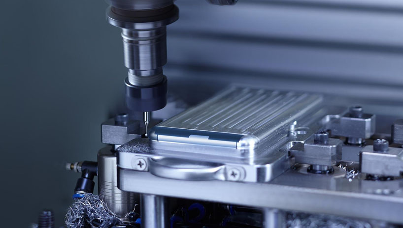
In CNC machining, precision is not limited to dimensions alone. The surface integrity and edge quality of a component often determine its real-world performance. Even the most accurate dimensions lose value when tiny imperfections such as burrs appear along machined edges. These unwanted metal projections may seem minor, but they can cause fitting issues, weaken assemblies, or compromise the functionality of high-performance parts.
Machining Burrs Formation & Deburring
Burrs typically form when excess material plastically deforms instead of shearing cleanly during cutting. The presence of burrs affects not only the final appearance of a part but also its function, assembly, and reliability. For example, a single unremoved burr can prevent tight sealing in hydraulic valves, interfere with micro-assembly in medical devices, or damage moving interfaces in automotive systems. As industries continue to demand tighter tolerances and smoother finishes, effective burr management becomes a crucial part of precision manufacturing.
Burr control is particularly vital in fields such as aerospace, automotive, and medical device manufacturing, where even minor defects can lead to system failures or safety hazards.
Understanding Burrs in CNC Machining
Burrs are small, irregular projections of material that remain attached to the workpiece after machining. They are created when the material undergoes plastic deformation instead of clean separation during the cutting process. While burrs are often only a few micrometers in size, their impact can extend far beyond appearance, influencing precision, performance, and even safety. In a production environment where hundreds of parts are machined daily, unnoticed burrs can lead to repeated assembly failures, tool wear, and downstream rework.
Definition and Characteristics of Burrs
A burr is typically formed along the edge of a machined surface, at the entrance or exit of a hole, or around intersections of machined features. It occurs when the work material flows beyond the intended edge before fracturing, leaving a thin ridge or flap of metal. The size and shape of burrs depend on cutting conditions, material properties, and tool geometry. Softer, ductile materials like aluminum and copper tend to form longer burrs, whereas harder alloys may produce smaller yet sharper edges.
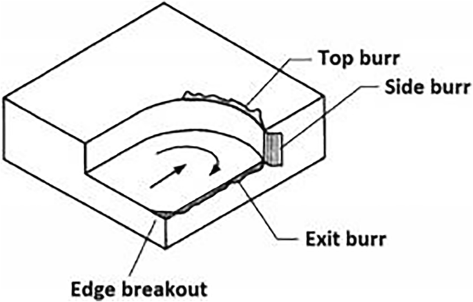
Types of Burrs
Burrs appear in different forms depending on the machining operation. Recognizing these types is essential for selecting effective control strategies.
- Roll-over burrs: Formed when material flows over the tool’s exit edge, common in milling and turning operations.
- Tear burrs: Caused by excessive deformation or tool wear, resulting in partially torn material at the surface.
- Side burrs: Appear on the side of a machined edge, often due to lateral tool forces in milling.
- End burrs: Found at the termination points of a cut, especially in drilling or slotting, where the tool exits the material.
Each burr type has a different formation mechanism and, therefore, a different removal or prevention approach. For example, roll-over burrs can often be reduced by optimizing tool exit paths, while tear burrs may require tool sharpening or parameter tuning.
Impact on Dimensional Accuracy and Surface Quality
Even though burrs may seem superficial, they interfere directly with part tolerances. A thin metal flap along a precision edge can alter the measured dimension or obstruct mating parts during assembly. Burrs also degrade surface finish, making sealing surfaces or sliding interfaces unreliable. In industries where micro-scale precision is required, such as optics or medical devices, burrs can make a part entirely unusable.
Influence on Assembly and Product Performance
When burrs remain on parts, they can lead to poor assembly fits, increased friction, or even damage to adjoining components. In fluid or pneumatic systems, a single burr can detach during operation and block passages, leading to failure. For moving mechanisms, burrs may accelerate wear by acting as abrasive particles.
Comparison Across Machining Processes
Different machining processes tend to generate different burr characteristics:
- Drilling: Produces burrs mainly at the hole exit due to chip deformation and tool breakthrough.
- Milling: Forms burrs along edges, corners, and shoulders, especially at the tool exit side.
- Turning: Creates burrs at part ends, grooves, and chamfers during tool disengagement.
In general, burr formation increases with tool wear, excessive feed, and unstable exit conditions. Understanding these differences helps machinists predict where burrs are likely to appear and adjust process parameters accordingly.
Burrs may seem inevitable, but recognizing their types, locations, and impacts is the first step toward effective control. Once their behavior is understood, process engineers can trace them back to their sources,
Causes of Burr Formation
Burrs do not occur randomly. They form as a result of specific interactions between the material, tool, cutting conditions, and the machine’s rigidity. Understanding these factors helps in identifying whether the burrs stem from material properties, tool condition, or machining setup. Once the origin is identified, corrective measures can be applied efficiently without unnecessary rework or trial runs.
Burr formation is primarily caused by plastic deformation at the cutting edge, where the material fails to separate cleanly. Instead of breaking off, part of the metal bends and adheres to the edge of the machined surface. This section examines each contributing factor in detail.
Material Factors
Material properties have a direct influence on burr generation. Ductility, hardness, and grain structure determine how the metal behaves under shear stress.
Hardness and Ductility
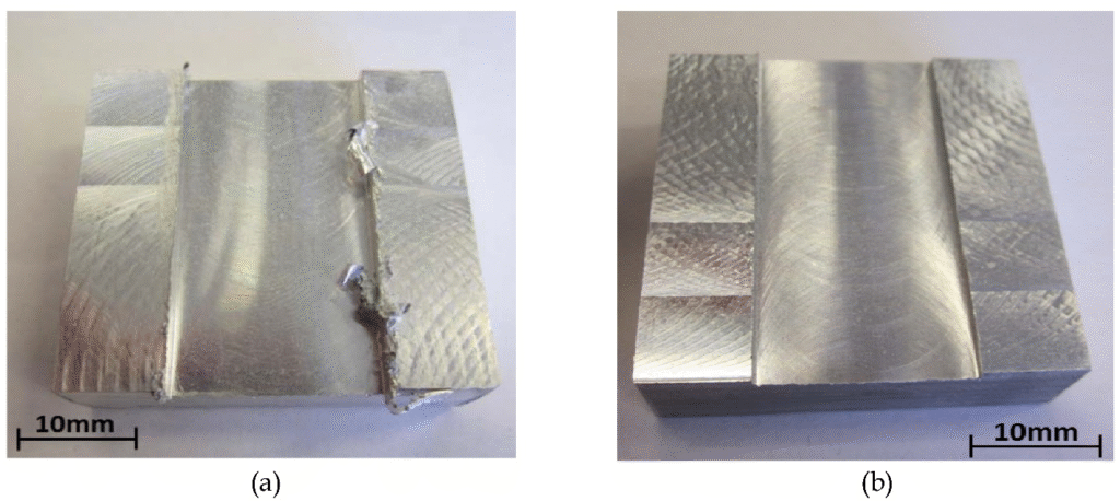
Soft and ductile materials, such as aluminum, brass, and copper alloys, tend to form larger burrs because they deform easily before fracture. In contrast, harder materials like tool steel or titanium resist plastic deformation, often producing smaller but sharper burrs. Excessive hardness, however, can also promote micro-chipping, creating rough, jagged edges that require secondary finishing.
Grain Direction and Anisotropy
In materials with directional grain structures, such as rolled sheet metals or extruded bars, burr formation varies depending on the cutting direction. When machining across the grain, the material may tear instead of shearing cleanly, increasing the likelihood of burr formation. This is especially critical in aerospace-grade alloys, where anisotropy affects both tool wear and burr behavior.
Tool Factors
Tool geometry and condition play a crucial role in burr formation. Even a well-set machine can produce excessive burrs if the cutting edge is not properly maintained.
Tool Geometry
The rake angle, clearance angle, and nose radius influence how the chip flows and separates from the workpiece.
- A positive rake angle reduces cutting forces and helps chips flow smoothly, minimizing burrs.
- A larger nose radius improves surface finish but may cause greater material flow, creating larger burrs if not balanced properly.
- Insufficient clearance angle leads to rubbing and plastic deformation near the edge.
Tool Wear and Coating
As tools wear, their edges round off and lose sharpness. A dull cutting edge smears the material rather than cutting it, leading to thick, rolled burrs. The right tool coating, such as TiAlN or DLC, reduces friction and heat buildup, extending tool life and minimizing burr size. Monitoring tool wear through visual checks or spindle load analysis helps detect early signs of burr-related quality decline.
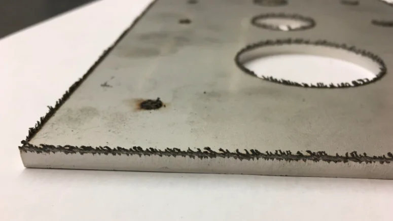
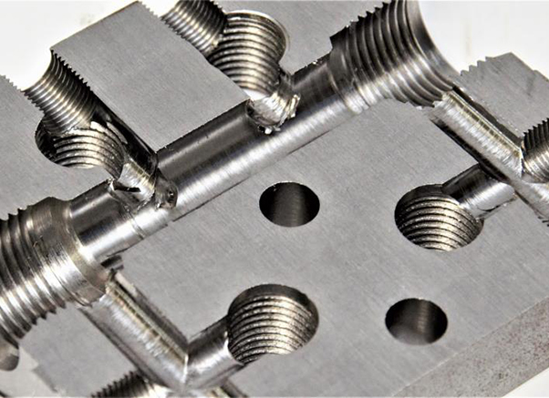
Burrs of Elevator SS Sheet Metal Parts
Process Parameters
Cutting parameters directly control how the tool engages the material and influence burr formation at both the entry and exit edges.
Cutting Speed and Feed Rate
Low cutting speeds can cause material to stick to the tool edge, increasing burr size. Conversely, excessively high speeds raise cutting temperature, softening the workpiece and promoting plastic deformation. A moderate, optimized cutting speed minimizes both effects. Similarly, a feed rate that is too high increases cutting forces, while a very low feed rate causes rubbing, both resulting in burrs.
Depth of Cut and Tool Engagement
A shallow depth of cut may leave uncut material along edges, which becomes a burr when the tool exits. In contrast, deeper cuts with proper coolant flow can reduce thermal distortion, improving chip separation. Maintaining consistent engagement reduces tool deflection and helps produce clean edges.
Interrupted Cuts and Tool Direction
Interrupted cutting paths, such as when machining slots or intersecting holes, tend to produce burrs at entry and exit points. Adjusting the tool direction to exit along a support edge or using climb milling instead of conventional milling often minimizes this issue.
Machine Factors
Machine rigidity and spindle alignment determine how stable the cutting process remains. Even slight vibrations can cause uneven chip formation and excessive burrs.
Rigidity and Structural Stability
A machine with low stiffness or worn bearings allows tool deflection, which changes the cutting angle at the point of contact. This instability promotes inconsistent chip formation, leading to varying burr sizes along the edge. Ensuring tight gibs, balanced spindles, and proper fixture design is essential for minimizing movement during cutting.
Vibration and Chatter
Chatter marks often accompany burr formation. When vibrations occur, the tool intermittently loses and regains contact with the workpiece, tearing instead of cutting. Proper damping, balanced tooling, and optimized cutting parameters help eliminate chatter-induced burrs.
Process-Specific Factors
Each machining process exhibits unique burr formation behavior based on how the cutting edge interacts with the material.
Drilling
In drilling, burrs primarily form at the hole exit where the tool breaks through the material. The thinning wall at the breakthrough cannot support the cutting force, causing material to stretch and roll outward. Reducing feed near the exit or using backup plates can minimize this effect.
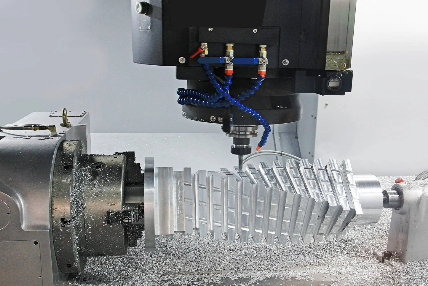
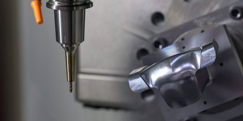
Milling
During milling, burrs typically appear along the tool’s exit side where the cutter disengages. Sharp corners and slot edges are especially prone to burrs due to chip curling and uneven load distribution. Adjusting the toolpath strategy, such as using climb milling and finishing passes, helps reduce edge deformation.
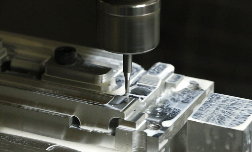
Burrs In Milling Aluminum In Machining Centers
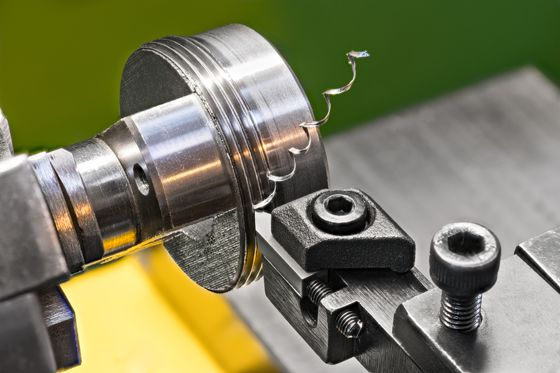
Turning
In turning, burrs form at part ends, shoulders, and chamfers when the tool retracts or crosses an edge. These burrs can often be controlled by adding a chamfering toolpath or adjusting the feed near the tool exit point.
Burr formation is the combined outcome of material response, cutting conditions, and mechanical stability. Addressing only one factor rarely solves the problem. Instead, a balanced approach involving proper tool geometry, stable machine setup, and optimized parameters ensures burrs are minimized at their source.
Burr Inspection and Measurement
Burr inspection is an essential part of quality control in CNC machining. Detecting and quantifying burrs helps determine whether a part meets dimensional and surface integrity standards. Since burrs can vary widely in size and appearance, inspection methods must be both precise and consistent. Without a structured inspection process, burr-related defects often pass unnoticed until they affect assembly or performance.
Inspection typically involves three key stages: visual identification, measurement, and documentation against set tolerances. Each stage plays a role in maintaining accuracy across production batches and ensuring repeatable results.
Visual Inspection
Visual inspection is the most common and immediate way to detect burrs. It provides a quick assessment of burr location, severity, and type, allowing machinists or inspectors to identify recurring issues linked to tools or cutting parameters.
Inspection Setup and Conditions
To ensure consistency, lighting and magnification must be properly controlled. Using bright, angled illumination reveals fine burrs that are invisible under direct light. A consistent viewing angle prevents shadow-related misjudgments. Magnifiers or low-power microscopes (10x–30x) are useful for inspecting small or critical parts.
Identifying Burr Type and Location
Trained inspectors can classify burrs visually based on appearance and position. Roll-over burrs show as thin lips curling outward, while tear burrs appear ragged and irregular. Locations most prone to burrs include hole exits, groove edges, and transitions between flat and curved surfaces.
For complex parts, photographs or 3D scans of typical burr sites can help operators recognize patterns during in-process checks.
Advantages and Limitations
Visual inspection is fast and cost-effective, but subjective. Results depend on the inspector’s experience, eyesight, and lighting. Therefore, visual inspection should serve as the first screening step before quantitative evaluation.
Measuring Burr Size
Once burrs are detected, quantifying their dimensions is necessary for determining if they fall within acceptable limits. Burr measurement focuses on height, width, and sometimes root thickness.
Measurement Tools
- Calipers and Micrometers: Suitable for larger burrs, though precision is limited.
- Profilometers: Measure burr height and shape along a surface trace. Contact-type profilometers can capture burr peaks but may damage delicate edges, so non-contact laser profilometers are preferred for micro-scale burrs.
- Optical and Digital Microscopes: Provide accurate 2D and 3D profiles of burr geometry, useful in research and process optimization.
- Coordinate Measuring Machines (CMM): Ideal for dimensional inspection when burrs affect overall part geometry.
Quantitative Parameters
Three main dimensions define a burr:
- Burr height: Distance from the original edge to the burr tip.
- Burr width: Distance from the burr’s root to its farthest lateral edge.
- Burr volume: Estimated for critical parts using 3D scanning or image analysis.
Measuring these parameters helps engineers compare burr characteristics before and after parameter adjustments, improving process control.
Integration into Quality Control
Burr measurement data should be recorded alongside tool wear and cutting conditions. Correlating these variables allows engineers to identify trends, such as increasing burr height after certain tool life cycles. Automating data collection through digital microscopes or vision systems strengthens statistical process control (SPC) and ensures consistency across operators.
Standards and Tolerances
Defining burr acceptance criteria is crucial in industries where sharp edges can affect safety or performance. Relying on visual judgment alone creates inconsistency between shifts or suppliers, so standards provide measurable guidelines.
Industry Standards
Organizations such as ISO and ASTM define methods for burr characterization and surface integrity evaluation. For example:
- ISO 13715: Specifies edge conditions and permissible burrs on technical drawings.
- ASTM B600: Guides visual inspection of surface imperfections on metallic parts.
These standards help unify expectations between manufacturers and clients, ensuring consistent quality across production sites.
Setting Internal Tolerances
In practice, each company may establish its own burr tolerance levels depending on product function. For example:
- Hydraulic components may allow a maximum burr height of 0.02 mm.
- Precision optical mounts may require burr-free edges entirely.
Documenting these tolerances in control plans and inspection sheets prevents ambiguity during final checks.
Documentation and Record Keeping
Inspection results should be traceable. Photos, measurement data, and inspection reports can be attached to part records in quality management systems (QMS). When burr-related defects occur, this documentation helps identify the root cause quickly, whether it was tooling, parameter selection, or operator oversight.
Burr inspection and measurement form the foundation for quality assurance in CNC machining. Visual checks identify defects early, while quantitative measurements provide traceable data for improvement. By establishing standardized methods and tolerance documentation, manufacturers can maintain consistency, reduce rework, and move confidently into the next stage, selecting the best removal techniques for lasting results.
Burr Removal Techniques
Burr removal is one of the most time-consuming secondary operations in CNC machining. Even with advanced tooling and optimized processes, small burrs are inevitable in many cutting applications. The key to efficiency lies in choosing the right removal method for the material, geometry, and production volume. Removing burrs not only improves the part’s appearance but also ensures safety, proper assembly, and long-term reliability.
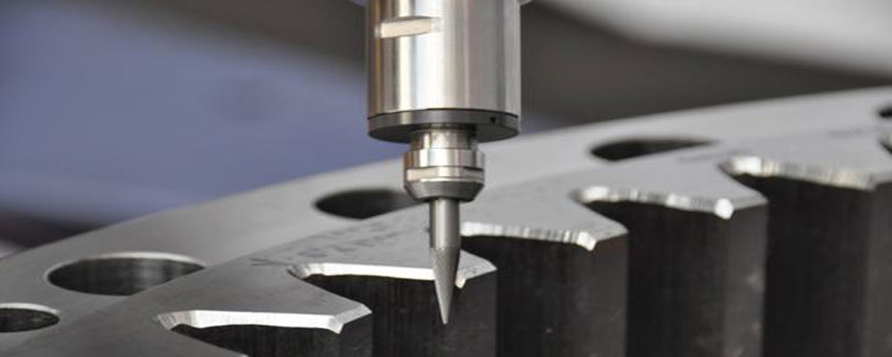
How To Reduce Burrs During Machining
Effective deburring depends on three main considerations: when to perform it (during or after machining), how aggressive the method should be, and how it integrates into production flow. Each approach carries trade-offs in cost, cycle time, and consistency.
In-Process Deburring
In-process deburring refers to removing or minimizing burrs during the machining operation itself. The main advantage is that parts leave the machine ready for inspection or assembly without additional handling. This approach saves time and prevents surface damage caused by manual finishing.
Principle and Advantages
In-process deburring modifies the cutting path, tool design, or machining strategy to smooth sharp edges as they are created. It ensures burrs never reach a problematic size. Integrating deburring into the CNC program improves repeatability, especially in high-volume production.
Key benefits include:
- Reduced manual labor and handling.
- Better consistency between parts.
- Lower risk of part contamination or scratches.
- Improved tool utilization and shorter overall cycle times.
Common Techniques
- Chamfering and Edge Finishing: Small chamfers or radius cuts are programmed directly into the toolpath to remove burrs at the exit edge. Chamfer mills or corner-rounding tools are often used.
- Specialized Inserts: Tools with cutting edges designed for back-chamfering or cross-hole deburring can clean internal intersections in a single pass.
- Toolpath Optimization: Modifying entry and exit points or switching from conventional to climb milling reduces exit burrs.
- High-Pressure Coolant: Efficient chip evacuation prevents recutting of loose burr fragments that can form secondary burrs.
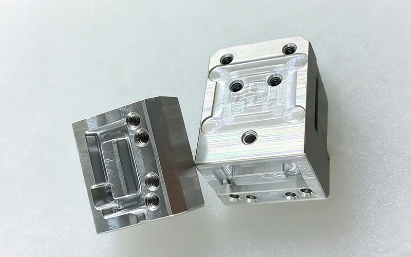
Applications
In-process methods are ideal for parts with simple geometries or open edges, such as turned shafts or milled brackets. For intricate parts with cross-holes or internal cavities, additional post-process steps are still required.
Post-Process Deburring
Post-process deburring is performed after machining is complete. It is necessary for parts with complex shapes, internal passages, or tight tolerances where burrs remain inaccessible during cutting. This stage includes a wide range of mechanical, thermal, and chemical techniques.
Manual Deburring
Manual deburring uses hand tools such as files, scrapers, blades, or abrasive cloths. Skilled operators can remove burrs precisely, especially from intricate features.
Advantages include flexibility and minimal setup time. However, it is slow, inconsistent, and heavily dependent on operator skill. For large batches, manual work adds significant cost.
Mechanical Methods
Mechanical deburring uses machines or tools that apply controlled abrasion to remove burrs uniformly. Common mechanical methods include:
- Tumbling: Parts are rotated with abrasive media in a drum, smoothing edges and surfaces simultaneously.
- Vibratory Finishing: Similar to tumbling but uses vibration to move parts and media, offering finer control.
- Brushing: Rotary brushes or abrasive nylon wheels remove light burrs from flat surfaces or holes.
- Abrasive Blasting: Propelled media such as glass beads or aluminum oxide clean edges and internal corners.
Mechanical processes are efficient for batches of small parts and provide uniform finishes, though they can dull sharp edges if not carefully controlled.
Thermal Deburring (TEM)
Thermal deburring removes burrs using controlled combustion of a gas mixture. The intense heat burns off thin burrs instantly without affecting the base material.
It is best suited for internal or hard-to-reach areas, such as hydraulic manifolds or intersecting passages. While extremely effective, TEM requires specialized equipment and safety controls.
Electrochemical Deburring (ECD)
ECD uses electrolysis to dissolve burrs selectively. A tool electrode is positioned close to the burr area, and an electric current removes material chemically.
It offers high precision and is effective for deburring hardened materials or internal geometries. ECD produces clean, burr-free surfaces without mechanical stress, though setup costs are high.
Abrasive Flow Machining (AFM)
AFM passes a semi-solid abrasive medium through internal channels to smooth and polish surfaces. It is commonly used in aerospace and medical components that require clean internal flow paths. The process also removes micro-burrs that other methods may miss.
Choosing the Right Method
Selecting a suitable deburring technique depends on material type, part geometry, production volume, and cost targets. Each method has its strengths and limitations, so balancing precision with practicality is essential.
Key Selection Criteria
- Part Geometry: Complex parts with cross-holes or cavities often require electrochemical or thermal methods, while flat parts benefit from mechanical or in-process approaches.
- Material: Soft alloys respond well to brushing or vibratory finishing, while hard materials may require electrochemical or abrasive flow processes.
- Production Volume: Manual deburring suits prototypes or small batches, whereas automated mechanical or in-process methods are better for mass production.
- Cost and Consistency: Processes like TEM or ECD offer precision and repeatability but involve high initial costs. For general production, mechanical or in-process deburring often provides a balanced solution.
Comparison of Approaches
| Aspect | In-Process Deburring | Post-Process Deburring |
| Cycle Time | Integrated, shorter overall | Requires additional handling |
| Precision | High for open edges | High for internal or complex areas |
| Cost | Lower long-term cost | Higher operational cost |
| Suitability | Best for simple geometries | Best for complex components |
Integration into Workflow
Efficient burr removal involves combining techniques. For example, an in-process chamfer pass can handle external edges, followed by vibratory finishing to polish surfaces. Coordinating these steps minimizes manual intervention and ensures consistent part quality.
Burr removal is both a technical and economic challenge in CNC machining. The right combination of methods ensures clean, safe, and functional parts without excessive time or labor. However, removing burrs should never be the only goal.
Quality Control and Continuous Improvement
Maintaining burr-free production requires more than occasional inspection or tool replacement. It depends on a structured quality control (QC) framework that tracks burr trends, identifies their causes, and integrates feedback into process planning. Continuous improvement ensures that burr prevention becomes part of the machining culture rather than a temporary corrective action.
A comprehensive burr control program combines data collection, process evaluation, and employee involvement. Each stage of machining, from setup to final inspection, contributes to maintaining consistent edge quality and reducing post-processing time.
Monitoring Burr Formation Trends in Production
Regular monitoring of burr behavior across production batches provides valuable insight into process stability. Burr size, frequency, and type often reveal early signs of tool wear or parameter drift.
Establishing Baselines
Every machine and material combination behaves differently. Establishing baseline burr measurements under optimal conditions allows easy comparison during future inspections. This helps identify when deviations occur before they lead to quality failures.
Data Collection and Analysis
- Record burr height, width, and location for each inspection lot.
- Track tool usage hours or parts produced per tool.
- Correlate burr changes with cutting parameters, coolant flow, and machine condition.
Data-driven monitoring helps distinguish between random variation and systematic problems. For instance, increasing burr height near the tool’s end-of-life period may indicate the need for earlier tool replacement intervals.
Visual and Statistical Tracking
Implementing control charts or simple burr classification diagrams can make burr monitoring part of daily shop-floor routines. Operators can easily note visual changes without complex measurement tools, providing real-time process awareness.
Incorporating Feedback into Process Planning
Quality control becomes more effective when inspection feedback directly influences future machining strategies. This feedback loop connects operators, engineers, and programmers in a continuous cycle of refinement.
Feedback Implementation Steps
- Identify recurring burr issues through inspection data.
- Trace them to the related factors, such as tool geometry, cutting parameters, or fixturing stability.
- Update CNC programs or tool setups to address the source rather than relying solely on deburring.
Cross-Functional Collaboration
Tooling engineers, machinists, and quality inspectors should jointly review burr data at regular intervals. Collaborative review meetings allow for practical changes based on both empirical data and operator experience. This shared responsibility ensures consistent improvement across shifts.
Documentation and Version Control
Revised toolpaths, setup sheets, and inspection results should be documented clearly. Maintaining version control of CNC programs prevents old methods from reintroducing previously solved issues.
Cost-Benefit of Proactive Burr Control
Investing time and resources in burr prevention and inspection provides measurable economic returns. While it may seem costly to modify setups or purchase specialized tools, the long-term savings in rework, inspection, and assembly justify the effort.
Direct Cost Savings
Reducing burr-related rework cuts manual deburring time and tool wear. Eliminating extra handling also lowers the risk of part damage. In mass production, even a small reduction in cycle time per part can translate into significant annual savings.
Indirect Benefits
- Improved part reliability reduces warranty claims and product recalls.
- Enhanced surface quality improves customer satisfaction and brand reputation.
- Fewer inspection failures lead to smoother workflow and higher machine utilization.
Quantifying these savings through cost-per-part analysis highlights how preventive measures outweigh the recurring expenses of manual deburring or re-machining.
Conclusion
Burrs may seem like minor machining imperfections, but their consequences can be significant. They affect assembly accuracy, surface integrity, and long-term reliability of components. By understanding how burrs form, implementing effective inspection techniques, and applying targeted removal and prevention strategies, manufacturers can achieve both precision and productivity.
Integrating burr control into quality management systems ensures continuous improvement. Every observation, measurement, and adjustment contributes to a more stable and predictable machining process. Ultimately, proactive burr management saves time, reduces costs, and strengthens confidence in the final product’s performance and appearance.