

CNC turning has become the backbone of modern precision manufacturing, where even a micrometer of deviation can separate a high-quality part from a rejected one. Every cut, feed, and contour depends on how accurately the machine interprets the tool’s geometry. In industries such as aerospace, medical, and automotive, where components often operate under extreme conditions, the smallest variation in dimension or surface finish can impact performance, safety, and longevity. That is why understanding and controlling every factor influencing accuracy is essential, and one of the most overlooked among them is the tool nose radius.
Tool Nose Radius Compensation in Precision CNC Turning
In simple terms, the tool nose radius is the curved tip of a turning insert that forms the transition between the cutting edges. While it may appear insignificant, this small radius influences how the tool contacts the workpiece, how stress distributes across the cutting zone, and how smoothly the final surface is generated. A properly selected and compensated radius ensures dimensional stability and surface quality, while an incorrect one can introduce tolerance errors that grow with every pass.
This is where Tool Nose Radius Compensation (TNRC) becomes critical. Without it, even a well-written program can produce inconsistent sizes or distorted profiles. This article explores the true role of tool nose radius compensation in precision CNC turning, what it is, how it works, why it matters, and how professionals use it to achieve repeatable accuracy across critical components.
Understanding Tool Nose Radius in CNC Turning
The tool nose radius is a small yet critical feature at the tip of a turning insert. Instead of ending in a sharp corner, the cutting edge transitions through a curved section known as the nose radius. This radius plays a vital role in defining how the tool interacts with the workpiece, influencing both the accuracy of the part and the quality of the surface finish. Understanding its geometry and behavior is essential for achieving consistent precision in CNC turning.
What is a Tool Nose Radius
In CNC turning, the tool nose radius refers to the rounded point that connects the side and end cutting edges of the insert. It defines the effective contact area between the tool and the workpiece during cutting. A perfectly sharp tip would concentrate stress at a single point, leading to rapid tool wear and poor surface quality. The nose radius distributes this stress more evenly, allowing smoother cutting action and improved tool life.
Different inserts are available with varying nose radii, typically ranging from 0.2 mm to 1.2 mm. Smaller radii are used for fine finishing, while larger ones are suited for roughing operations where material removal is prioritized over surface finish. Choosing the right radius depends on the balance between accuracy, finish, and tool durability.
Impact on Surface Finish
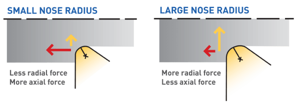
The tool nose radius directly affects the surface texture left on the workpiece. A larger radius produces a smoother finish because the tool moves in gentler arcs, reducing the height of feed marks. However, it also increases cutting forces, which can introduce deflection and vibration if the setup lacks rigidity.
- Larger radius: Creates smoother surfaces but increases cutting pressure.
- Smaller radius: Produces finer detail and lower cutting load but leaves visible feed marks.
For high-precision finishing, the radius must be chosen carefully to achieve the required surface roughness without compromising dimensional control. It is also important to synchronize the feed rate with the nose radius, as surface finish improves when feed per revolution is small relative to the tool radius.
Influence on Tolerances and Dimensional Accuracy
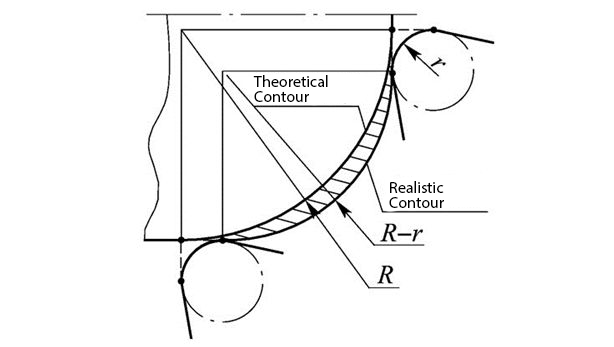
Even a small variation in the nose radius can subtly shift part dimensions. During turning, the machine interprets the tool path as if the cutting point were at a specific reference. If the tool has a larger or smaller radius than programmed, the resulting surface will deviate from the intended geometry.
For instance, an underestimated radius can lead to undersized parts, while an overestimated one produces oversized features. Over multiple passes, these deviations accumulate, affecting concentricity, cylindricity, and form accuracy. This is why accurate measurement and compensation of the tool nose radius are critical in maintaining tight tolerances.
Tool Nose Radius Compensation: What It Is and Why It Matters
Tool Nose Radius Compensation (TNRC) is a control function in CNC turning that allows the machine to account for the rounded tip of the cutting tool when generating the final part geometry. Without this compensation, the toolpath programmed in CAM or manually written G-code would assume a sharp cutting point. In practice, however, the cutting tip follows a curved profile. This small geometric difference can lead to errors in the final part dimensions if not corrected properly.
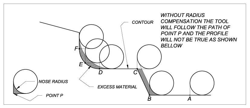
When the controller applies tool nose radius compensation, it adjusts the toolpath in real time so the actual cutting edge contacts the workpiece at the correct location. The CNC system effectively “shifts” the programmed path based on the tool’s nose radius and orientation, ensuring the produced contour matches the intended geometry on the drawing.
Why Compensation Is Necessary
Even minor deviations in tool nose radius can cause measurable tolerance drift. When precision requirements are within a few microns, an uncorrected radius can result in significant dimensional error or unwanted tapers. In high-accuracy production environments, such as aerospace and medical manufacturing, these variations are unacceptable.
Key reasons why compensation is critical:
- Prevents undersized or oversized parts by correcting for nose curvature.
- Eliminates profile distortion in contour turning and facing operations.
- Improves repeatability between different machines or setups using the same program.
- Reduces time spent manually adjusting offsets for each tool change.
Without TNRC, operators often rely on trial and error to “chase” size, which wastes time and increases scrap. With proper compensation, the machine produces accurate results directly from the first finished part.
Types of Compensation
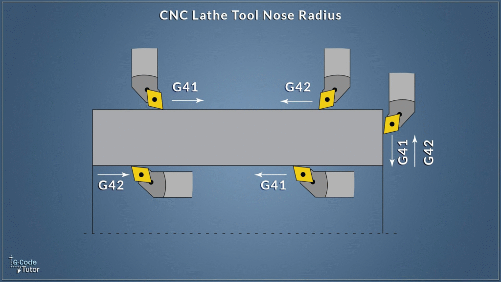
Tool nose radius compensation is implemented primarily using the G41 and G42 commands in CNC programming. These commands instruct the controller on which side of the toolpath to offset the tool tip.
- G41 – Left Compensation: The control offsets the tool to the left of the programmed path.
- G42 – Right Compensation: The control offsets the tool to the right of the programmed path.
Choosing the correct direction depends on the tool’s orientation and the direction of tool movement. A simple mistake in selecting G41 or G42 can lead to gouged surfaces or reversed profiles.
Beyond this, compensation can be categorized based on where and how it is applied:
- Manual Compensation: The programmer calculates and enters the offsets directly in the G-code. This method offers full control but is prone to human error.
- Automatic Compensation: The machine or CAM software automatically applies the compensation based on tool data and geometry input. This is more consistent, especially in complex parts.
Importance of Consistency and Process Reliability
Consistent use of TNRC ensures uniformity across multiple parts, even when tools are replaced or programs are reused. It creates a stable link between digital programming and physical machining, allowing the same program to produce identical parts across machines with different tool setups.
This consistency directly affects:
- Dimensional reliability: Reduces variation in size and form between parts.
- Surface integrity: Maintains uniform contact conditions, minimizing tool marks.
- Quality control efficiency: Lowers the need for manual measurement corrections.
When properly applied, TNRC transforms precision turning into a predictable process rather than a manual adjustment exercise. It helps machinists focus on optimization instead of troubleshooting dimensional errors.
Programming-Level vs. Machine-Level Compensation
Tool nose radius compensation can be managed in two main ways: at the programming level or at the machine level. Both aim to achieve the same goal, ensuring that the tool’s curved tip cuts exactly where intended, but they differ in how and when adjustments are applied. Understanding this distinction is essential for maintaining accuracy and reducing the risk of dimensional variation in precision CNC turning.
When compensation is applied during programming, the toolpath generated by CAM software already includes corrections for the tool nose radius. At the machine level, the CNC controller performs these corrections automatically based on tool data and offset parameters. Each method has unique advantages and potential drawbacks, and choosing the right one depends on the application, production volume, and accuracy requirements.
Programming-Level Compensation
In programming-level compensation, the tool nose radius is factored into the G-code before it ever reaches the CNC controller. This is typically done through CAM software or by manual calculation in custom code.
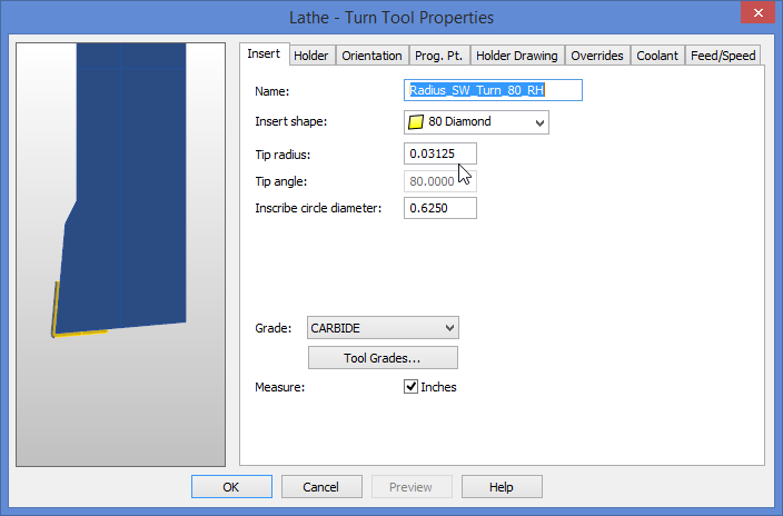
Tool Nose Radius Compensation in Feature CAM
This approach gives the programmer full control over how the compensation is applied. The path is visually simulated, and the tool’s movement relative to the part geometry can be verified before machining begins.
Advantages of Programming-Level Compensation:
- Pre-simulation accuracy: The effect of the nose radius is visible during toolpath verification, reducing the chance of unexpected tool motion.
- Consistency in digital workflow: Once validated, the same code can be used across machines with minimal variation.
- Detailed path control: Ideal for parts with complex contours or when multiple operations require precise blending.
Drawbacks:
- Limited flexibility on the shop floor: Any change in tool radius or insert geometry requires reprogramming or code editing.
- Human dependency: Manual entry of radius values increases the risk of data entry errors.
- No real-time adjustment: The controller cannot dynamically compensate for wear or small variations during machining.
Use Cases
Programming-level compensation is often preferred when producing prototype parts or small batches, where the same program may not be reused frequently. It is also suitable for complex contouring operations that require extensive verification before cutting, as simulation tools in CAM software can visually confirm accuracy.
Machine-Level Compensation
Machine-level compensation relies on the CNC controller to apply the correction during cutting. Instead of embedding compensation into the G-code, the programmer activates compensation commands (G41 or G42) and inputs the nose radius and tool orientation in the tool offset table. The machine then performs the calculation internally.
This approach allows operators to make adjustments directly on the control panel without editing the program. It is particularly effective for high-volume or repetitive production where tool wear and insert changes are frequent.
Advantages of Machine-Level Compensation:
- Dynamic correction: The controller adjusts automatically to the input radius, ensuring accurate cuts even if the tool is replaced.
- Less programming effort: The same G-code can be reused across machines with different tool setups.
- Faster adjustments: Operators can fine-tune wear offsets in seconds without halting production.
Drawbacks:
- Dependence on calibration: The system’s accuracy relies heavily on the correct radius and orientation being entered.
- Limited visibility before machining: Errors may not appear until the first test cut is made.
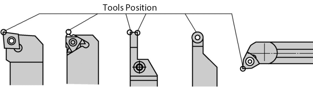
- Training requirement: Operators must understand how compensation directions (G41, G42) interact with tool orientation.
Practical Considerations
Machine-level compensation is common in production environments where flexibility and efficiency are priorities. It allows machinists to swap inserts, update radius values, and continue machining without editing code. This method also benefits multi-machine operations, where one master program runs on several lathes, each with its own offset table.
Comparison and Best Practices
Both compensation methods are effective when applied correctly. The choice depends on how much control and flexibility are required. For high-mix, low-volume work, programming-level compensation offers better visualization and safety. For high-volume production, machine-level compensation provides quicker setup and greater adaptability.
When to use programming-level compensation:
- When producing prototype parts or small batches.
- When part geometry involves complex contours that require pre-simulation.
- When using custom tools or non-standard nose shapes.
When to use machine-level compensation:
- When running long production batches.
- When tools are frequently changed or re-sharpened.
- When multiple machines share the same program.
Combining both methods:
In some cases, both methods are used together. CAM software may include the nominal compensation path, while fine-tuning occurs through the CNC controller’s wear offsets. This hybrid approach ensures maximum precision while maintaining flexibility for real-world adjustments.
Practical Applications in High-Precision Industries
Tool nose radius compensation is not just a theoretical control feature. It directly affects how precision parts are produced across industries that rely on exact geometry, repeatable accuracy, and fine surface finishes. In sectors such as aerospace, medical device manufacturing, and automotive engineering, even the smallest deviation in the tool path can lead to functional failure, vibration, or premature wear of components. Understanding how tool nose radius compensation supports these applications helps illustrate its real-world value in high-precision machining.
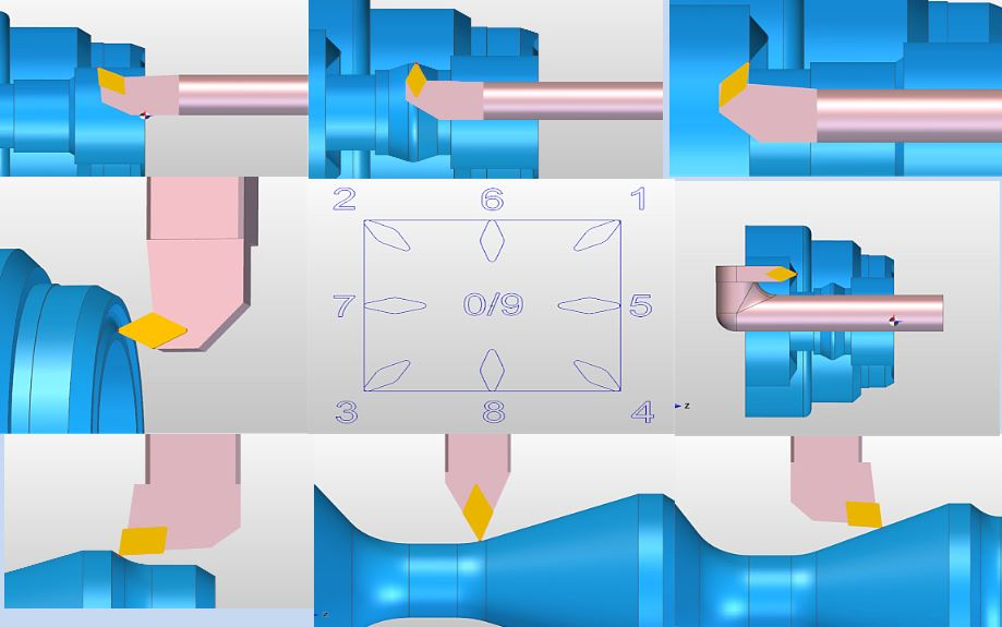
Tool Compensation Function for CNC Lathe Machining
Aerospace Shafts
Aerospace components are often long, slender, and machined to micrometer-level tolerances. Shafts used in turbines, actuators, and landing gear systems must maintain straightness, roundness, and balance under high rotational speeds. Any inconsistency in tool geometry can introduce taper, chatter marks, or uneven stress distribution.
Tool nose radius compensation ensures the tool follows the exact contour designed for the shaft’s surface, preventing undersized or oversized diameters. This control becomes especially important during finishing passes, where the depth of cut is minimal and even a minor offset error can push a part out of tolerance.
Key aspects influenced by tool nose radius compensation in aerospace machining:
- Dimensional precision: Maintains diameter consistency across long cuts and blended radii.
- Surface integrity: Reduces micro-tears and feed marks that can initiate fatigue cracks.
- Stress distribution: The correct radius ensures even load transfer across contact surfaces, improving fatigue resistance.
For example, a typical titanium aircraft shaft may require surface roughness below Ra 0.2 µm and diameter tolerance within ±0.005 mm. These levels of precision are only achievable when the tool geometry is perfectly compensated throughout the toolpath.
Medical Implants
In medical manufacturing, parts such as orthopedic screws, bone plates, and joint implants are often made from titanium, cobalt-chromium alloys, or stainless steel. These materials are tough and difficult to machine cleanly without generating burrs or surface damage. The tool nose radius plays a major role in managing these challenges.
Tool nose radius compensation allows precise contouring of complex shapes such as hip stems, dental implants, and spinal cages. Because these components must meet strict biocompatibility standards, the surface finish must be uniform and free from irregularities that could trap biological residues or interfere with tissue integration.
Benefits of compensation in medical machining:
- Precision in micro-geometry: Ensures threads, fillets, and blend radii match design specifications.
- Enhanced surface quality: Maintains smooth finishes necessary for polishing and passivation.
- Repeatability: Allows consistent results across multiple batches and machines.
A small misalignment in the nose radius can distort the thread profile on a bone screw or create mismatched curvature in an implant, leading to rejection. Properly calibrated compensation ensures the machine reproduces the digital model with near-perfect accuracy.
Other High-Precision Components
Tool nose radius compensation extends to many other precision parts where geometric control and surface quality are crucial. In automotive, energy, and micro-mechanical industries, the tool’s effective radius influences how smoothly mating surfaces fit and how components perform under stress.
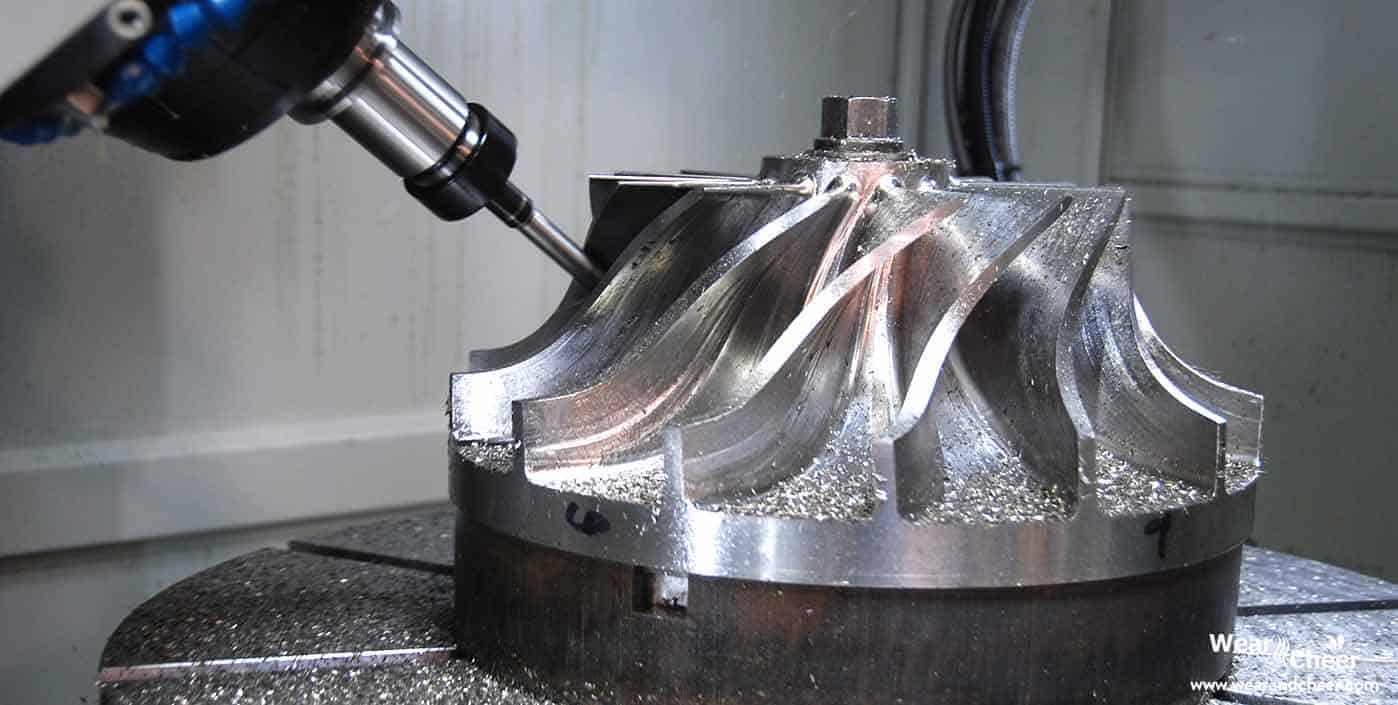
- Automotive turbochargers: The turbine shafts and bearing housings require perfect concentricity. Proper compensation prevents imbalance and vibration at high rotational speeds.
- Precision bearings: Consistent curvature of bearing races is critical for low friction and long service life. Compensation ensures roundness and profile accuracy during turning.
- Micro-mechanical parts: In miniature components, such as watch gears or sensor housings, even a 0.01 mm offset can distort geometry. Tool nose radius compensation enables stable cutting at extremely small scales.
Common Challenges and How to Overcome Them
Even when tool nose radius compensation is applied correctly, several practical challenges can still affect precision and process stability. These issues often arise from small oversights in setup, data entry, or tool wear monitoring. Understanding the causes and responses to these problems helps prevent cumulative dimensional errors and ensures consistent results across multiple parts and machines.
Tool Compensation Function for CNC Machining
Misalignment Between Program and Machine
One of the most frequent issues occurs when the toolpath programmed in CAM software does not match the setup on the actual machine. This misalignment usually happens due to incorrect tool orientation numbers, reversed compensation direction, or mismatched coordinate systems.
When this occurs, the control offsets the tool in the wrong direction, leading to cuts that are shifted or mirrored relative to the intended contour. In severe cases, this can cause gouging or undersized features.
Typical causes:
- Incorrect assignment of tool orientation codes in the offset table.
- The CAM software assumes a different tool direction than the physical setup.
- Using both CAM and machine-level compensation simultaneously.
Solutions:
- Always cross-check the tool orientation diagram on the CNC display with the actual turret position.
- Use a short trial cut to verify that the G41 and G42 commands offset in the correct direction.
- Avoid double compensation by ensuring that either CAM or the machine handles nose radius correction, but not both.
Coordination between the programmer and machinist is critical. A well-written setup sheet should specify the tool’s orientation, nose radius, and whether compensation is applied in the code or at the machine level. Clear documentation reduces misinterpretation during setup, especially when multiple people work on the same job.
Tool Wear and Changing Effective Radius
Over time, the tool’s cutting edge wears, altering the actual radius from its original value. Even a small reduction in radius affects the tool’s contact point and therefore the dimensional accuracy of the finished part. Worn tools can also create inconsistent surface finishes, particularly on precision components that require tight geometric control.
Effects of tool wear:
- Gradual size reduction in turned parts.
- Poor surface quality or feed marks due to loss of sharpness.
- Shift in tool contact angle, leading to taper or uneven profiles.
Mitigation strategies:
- Inspect tools after a predefined number of parts or cutting hours.
- Use in-process probing systems to measure reference diameters and automatically apply wear offsets.
- Replace inserts at consistent wear intervals instead of waiting for visible defects.
Some advanced facilities integrate tool life monitoring systems that use spindle load, vibration, or acoustic sensors to predict wear before it affects part quality. When the system detects a deviation in cutting force, it can alert the operator or trigger an automatic offset adjustment. This predictive approach keeps the tool nose radius compensation accurate without interrupting production.
Multiple Tool Changes and Offset Adjustments
High-mix production environments often involve frequent tool changes or insert replacements. Each time a tool is replaced, the effective radius and mounting position can vary slightly. Even small deviations in toolholder positioning can introduce dimensional differences if offsets are not updated.
Common challenges with tool changes:
- New inserts may have a slightly different nose radius than the previous batch.
- Manual re-entry of offsets increases the chance of data errors.
- Inconsistent torque on the toolholder can alter tool height and angle.
Solutions:
- Use presetting systems to measure each tool before installation and enter data automatically into the controller.
- Keep a standardized tool offset log to ensure consistent updates between operators.
- Verify offsets after every insert change with a quick test cut and measurement.
Many modern CNC machines allow tool data to be stored and transferred electronically between presetters and controllers. This automation eliminates manual input errors and ensures that compensation values remain accurate. When combined with barcode or RFID systems, tools can be identified instantly, and corresponding offset data can be recalled automatically.
Environmental and Thermal Factors
Thermal expansion of both the workpiece and machine components can subtly shift part dimensions. As the temperature rises during prolonged machining, tool position and size readings can change, even when compensation is correctly applied. These effects are particularly significant in long-run production or high-speed finishing operations.
Key concerns:
- Thermal growth of the spindle or turret affects tool position accuracy.
- Heat in the workpiece can cause temporary expansion, leading to apparent size errors.
- Coolant temperature fluctuations alter dimensional consistency.
Countermeasures:
- Use temperature-stabilized coolant systems to maintain constant cutting conditions.
- Allow the machine to reach thermal equilibrium before fine finishing passes.
- Implement in-process measurement routines that account for temperature variation and adjust offsets accordingly.
Precision shops often maintain controlled environments where temperature and humidity remain stable. Even a few degrees of variation can affect tolerance-critical parts. Proper compensation combined with environmental control ensures the highest level of repeatability.
Operator Oversight and Training Gaps
Even advanced compensation systems depend on operator awareness. Inadequate training or misunderstanding of how G41 and G42 commands interact with the tool setup can lead to unintentional errors. Overconfidence in automation without verification often results in undetected deviations until final inspection.
G41 and G42: Essential Cutter Compensation for CNC Lathes
Preventive actions:
- Provide structured training on interpreting compensation diagrams and offset logic.
- Encourage operators to perform initial dry runs and small-depth test cuts for verification.
- Implement a checklist before each production run to confirm compensation settings, tool data, and orientation.
Culture of Continuous Learning
Encouraging operators to document observations, share mistakes, and participate in problem-solving sessions helps develop a culture of precision. When machinists understand the reasoning behind compensation, they make fewer assumptions and more informed decisions.
Strategies for Mitigation
To maintain stable and reliable tool nose radius compensation across all conditions:
- Standardize the measurement and entry process for all tools.
- Use digital presetters and integrated data systems to reduce manual handling.
- Schedule periodic audits of tool offset data and calibration equipment.
- Combine automated measurement, operator training, and controlled environments for optimal results.
By addressing these common challenges, manufacturers can sustain high levels of dimensional accuracy and surface quality while minimizing downtime. Proper attention to detail and ongoing verification transform compensation from a reactive correction into a proactive quality control tool.
Conclusion
Tool nose radius compensation stands at the heart of precision CNC turning. It bridges the gap between programmed geometry and the real-world behavior of cutting tools, ensuring that every contour, diameter, and surface matches design intent. By correctly applying compensation, machinists eliminate size drift, reduce surface inconsistencies, and maintain the reliability of production runs across different machines and materials. In industries such as aerospace, medical, and automotive, where tolerances are measured in microns, proper compensation is not optional but essential for maintaining both safety and performance standards.
When supported by accurate tool measurement, disciplined verification, and continuous operator awareness, tool nose radius compensation transforms machining from a process of adjustment into one of control. It enables repeatable precision, smoother finishes, and improved efficiency throughout the production cycle. The best results come from integrating both programming and machine-level compensation with modern inspection practices and data-driven process monitoring. In essence, mastering tool nose radius compensation is mastering the art of consistency, the hallmark of every high-quality CNC-turned component.
